Confidential
Appendix 14
Epson WF-7620 / WF-7610 / WF-7110 Series Revision B
Note *1: The rotation directions of the PF Motor are as follows.
Clockwise: Paper is fed normally
Counterclockwise: Paper is fed backward
*2: The conditions of the CR lock are as follows.
Red CR lock is set
White CR lock is released
*3: If it cannot be initialized, the fatal error occurs.
*4: Confirm that the CR lock is not get stuck in the gap of the carriage or any other parts preventing the carriage from moving.
*5: Eject paper if any.
*6: Executed when the detected temperature is under 5
o
C (41
o
F) by the thermistor on the Printhead.
*7: The empty suction operation may occur depending on situations.
6. Low temperature operation sequence
*6
6-1.The CR Unit returns its home position.
6-2.The CR Unit moves between around the switch lever and in front of the Left Frame two times.
7. PF measurement and PW sensor initialization
7-1. The CR Unit slightly moves to the 0-digit side.
7-2.The carriage moves to the VHCheck position (130-digit side) quickly and stops; meanwhile the voltage values
detected by the PW sensor at the specified three points are recorded. At the same time, the PF Motor rotates
clockwise and measures the load.
7-3.The CR Unit detects the voltage of the PW sensor at the carriage stop position (the black area at the Paper Guide
Front).
7-4.The CR Unit returns near its home position. At the same time, the PF Motor rotates clockwise and measures the
load.
8. Detecting ink cartridge and initializing ink system
*7
8-1.The CR Unit slowly returns to its home position.
8-2.To check the operation of the PIS Sensor and to detect ink, the CR Unit moves back and forth between the CR Unit
and near the APG Lever for two times.
9. CR lock setting
9-1.The CR Unit moves to its home position.
9-2.The PF Roller rotates counterclockwise to lock the CR Unit with the CR Lock.
The power-on sequence shown in Table 1-1 is the sequence for when the previous power-off is
complete normally as indicated in the conditions. If the previous power-off ends abnormally,
operations including initialization of APG and such are performed in the following steps.
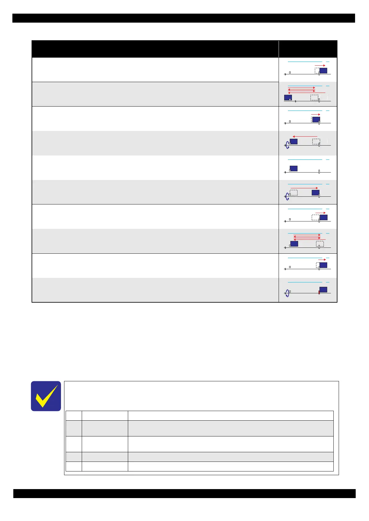
Table 1-1. Normal Power-on Sequence
Operation
*1
CR Unit/PF Roller
movement and position
*
2
0130 HP
0130 HP
0130 HP
0130 HP
0130 HP
0130 HP
0130 HP
0130 HP
0130 HP
1Prior to Step 4-1 Initializes the APG Lever.
2 Prior to Step 4-2
The CR Unit evacuates to the 130-digit side once, and the PF Roller rotates clockwise once, then the cap unit of
the Ink System is lowered, and then the CR Unit touches the Right Frame once again for confirmation.
3Prior to Step 4-3
The CR Unit moves to its CR Lock Position (130-digit side), and the PF Roller rotates
counterclockwise to engage the CR Lock. Then the CR Unit touches the CR Lock for confirmation.
4 Prior to Step 5-5 Initializes the APG unit (set to PG1 position).
5Prior to Step 7-1 Measurement of the CR Motor
 Loading...