17
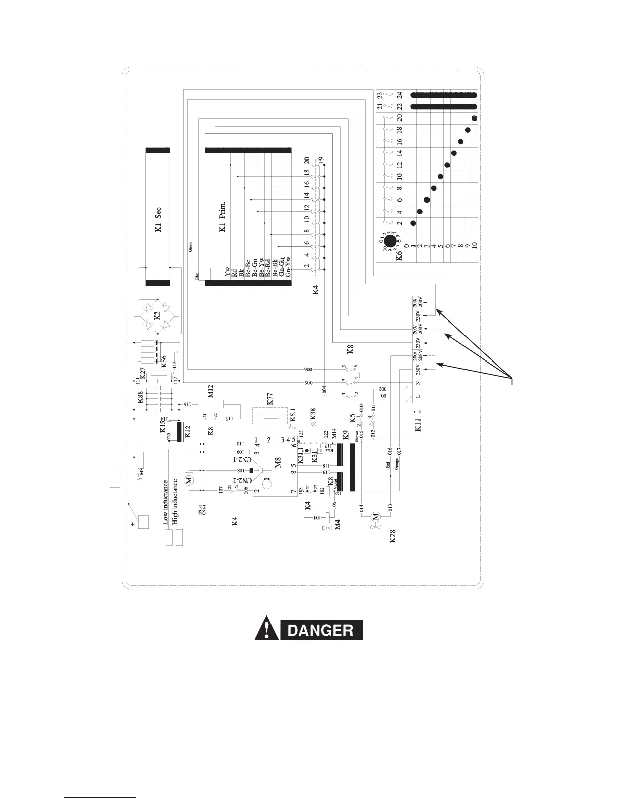
MigMaster 210 Electrical Drawing (1~ 208 / 230V)
Figure 4 - Electrical Diagram
The input terminal board at (K11) on Fig. 4 shows the 230V and 208V (dotted lines for the 208V change over).
Change over is made by removing the right side panel below the wire feed compartment and switching the primary
transformer taps on the terminal block. Both voltage taps (the 230V currently connected, and the (unused 208V
(200V) alternate) are marked with the input voltage requirement. All units are supplied from the factory for the highest
voltage (230VAC). Before switching the voltage taps, verify the actual voltage requirement as well as the current
voltage connection to be certain re-connection is necessary. If voltage tap re-connection is necessary re-connect as
indicated in the Electrical diagram above.
Only qualfied personnel should make these changes. Make certain the primary power has been disconnected
and all safety procedures have been followed before proceeding with these instructions.
Input Electrical Change Over - 230V to 208V
Input Electrical Change Over - 230V to 208V (200V)
OKC50* With a Short Lead