9
Installation
Recommended Wire Sizes (inches)
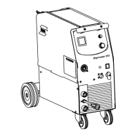
MigMaster 210
Mild Steel .023 -.035
Stainless Steel .030 - .035
Cored (gasless) .035
Unpacking
After unpacking, fit the wheels and gas bottle rack according to
the guide shown on page 13. Remove any covers over the
machine to ensure adequate cooling.
Electrical Connections
First make sure that the power supply is appropriately
fused (see Technical Data on page 8). Check that the
unit is connected for the appropriate main voltage. As
standard, the MigMaster 210 is connected for 230v-1
phase supply. Reconnecting should be done according
to the wiring diagrams on page 15. When connecting the
power plug, it is absolutely essential that the green/yellow
wire of the primary cable is connected to the earth screw
of the plug. The remaining two wires, live and neutral,
should be connected to the remaining two terminals in
the correct order.
Electrical connections should be made by a fully
qualified person.
Return Welding Cable And Clamp
The return cable should be firmly connected to the required
outlet terminal on the front of the machine. The clamp
should be clamped securely to the workpiece. Ensure all
connections are clean and tight to avoid welding defects.
Connecting The Welding Gun (See Fig. 1, pg.9)
The gun is connected to the Euro connector on the front
of the machine. Carefully align gas connection tube and
trigger connection pins with Euro adaptor on Mig gun.
Push in and tighten the lock nut. Be careful to line up gun
fittings correctly before tightening to avoid damaging
trigger pins and gas connection. Ensure that the Mig gun
is fitted with a wire conduit and contact tip suitable for the
size and type of wire being used. Refer to the Gun Manual
for spare parts
Feed Rolls
Make sure that the correct feed roll and grooves are used
for the dimension and type of wire being used. Each feed
roll has grooves for two dimensions of filler wire. The
feed roll
must be fitted with its size marking facing you.
The feed roll can be changed or replaced by removing the
screw in the centre of the hub.
“V’” groove rolls as supplied as standard for solid wire,
and serrated rolls for use with cored wire to ensure positive
feeding.
Welding Wire
Select a welding wire of the appropriate type and
size for the job at hand. See ESAB’s consumable
catalogue, available from your nearest ESAB Dis-
tributor, for a range of quality welding filler materials
and their recommended welding parameters.
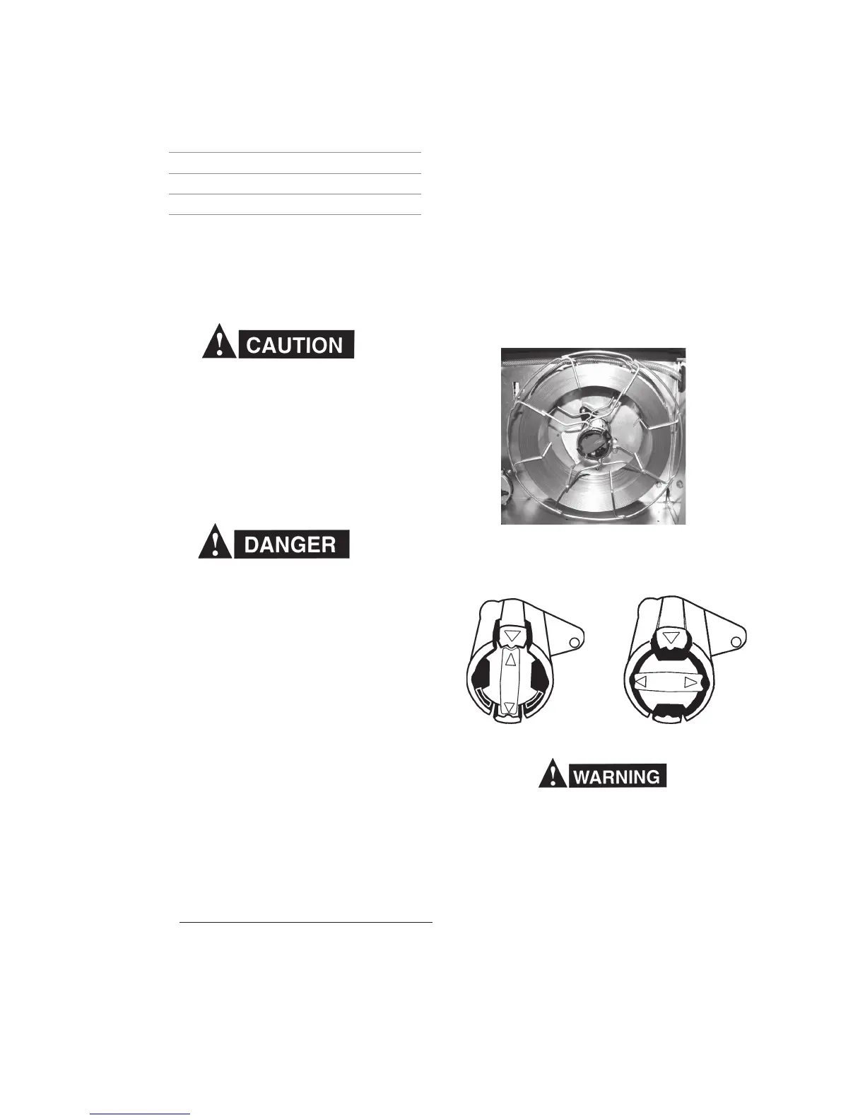
Fit the reel on to the hub so that the wire runs off at the
bottom into the wire guide. Two catches on the hub hold
the reel in place. It is in the lock position when the arrows
on the hub align with the arrows on the two catches (see
Fig. 2). To disengage the locking mechanism, twist the
center knob to the left (see Fig. 3). On a new reel, the
outer end of the wire is inserted through a hole and bent
over.
As with any work area, make sure safety glasses
with side shields are worn when handling or
changing wire or clipping wire off at the spool or
at the end of the torch. Hold onto the wire coming
off the spool with one hand before clipping.
Serious eye injury can result due to the springi-
ness of the wire which can quickly unravel, or a
cut wire end which may shoot across the room.
When loosening the wire from the hole, take care to hold
the coil so that it does not spring out and unravel. Cut off
the bent end of the wire, straighten the tip and then file off
any sharp edges so that the wire can run easily through
the soft wire guide of the welding conduit without
Fig. 1 - Mounted Welding Wire Reel
Fig. 2 - Locked
Fig. 3 - Unlocked