SECTION 2 INSTALLATION
11
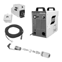
1. For operator safety, the torch connections are located
on the output terminal board behind the lower portion
of the front panel. Remove access door to output
terminal board from right panel of power source.
2. Thread the power cable, pilot arc cable and switch
lead of the PT-27 through the right open bushing of
the front panel. Connect power cable to the torch
fitting (left-hand threads); bolt the pilot arc cable ring
connection to the copper terminal; and plug in the
switch lead to the torch switch receptable on the
output terminal board. Make sure the power and
pilot arc cable connections are wrench-tight. Make
sure plug of switch lead is firmly locked in place.
3. Reassemble the access door to the power source.
4. Connect your air supply to the inlet connection of
the filter-regulator.
5. Clamp the work cable to the workpiece. Be sure
the workpiece is connected to an approved earth
ground with a properly sized ground cable.
Table 2-1. Recommended Sizes For
Input Conductors and Line Fuses
Input Requirements Input & Gnd Fuse
Volts Phase Amps Conductor Size
CU/AWG Amps
208 1 55A 6 80
208 3 26A/Ph. 6 50
230 1 49A 6 80
230 3 24A/Ph. 6 50
400 3 13 10 25
460 3 11 10 25
575 3 9 10 20
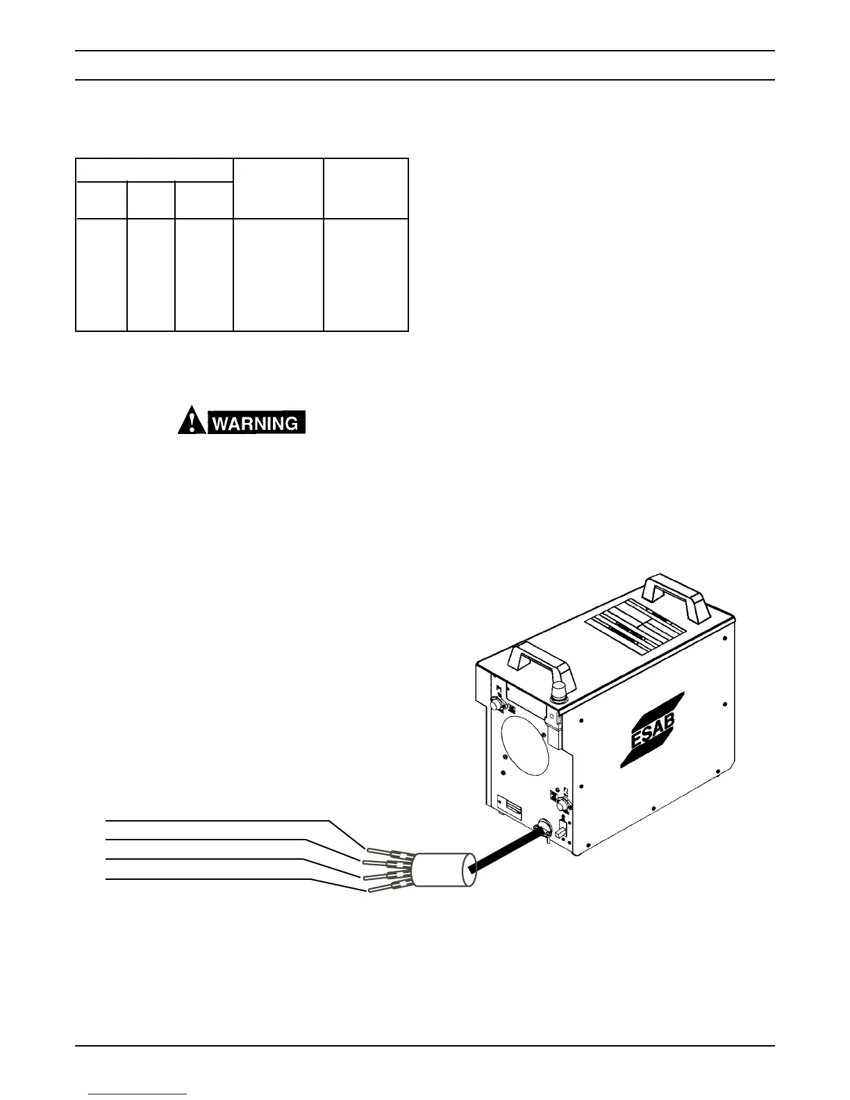
2.6 SECONDARY (OUTPUT) CONNECTIONS
(REFER TO FIG. 2-1)
Before making any connections to the power source
output terminals, make sure that all primary input
power to the power source is deenergized (off) at
the main disconnect switch and that the input power
cable is unplugged.
PRIMARY INPUT
POWER CABLE
Red - NOT USED ON SINGLE PHASE
White
Black
Green
 Loading...