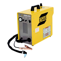
Do you have a question about the ESAB Plasmarc EPP-450 and is the answer not in the manual?
General safety warnings and precautions for maintenance procedures.
Instructions for cleaning the power source to ensure trouble-free operation.
Details on lubricating fans and fan motors.
General guidelines and safety precautions for troubleshooting the equipment.
Overview of front panel fault indicators and associated PCBs.
Diagnosing the Bus Ripple fault indicated by LED 3.
Diagnosing the High Bus fault indicated by LED 4.
Diagnosing the Low Bus fault indicated by LED 5.
Diagnosing the Arc Voltage Saturation fault indicated by LED 7.
Diagnosing the Arc Voltage Cutoff fault indicated by LED 8.
Explanation of the Power Reset fault indicator.
Diagnosing the right overcurrent fault indicated by LED 6.
Diagnosing the left overcurrent fault indicated by LED 9.
Diagnosing the left IGBT unsaturated fault indicated by LED 10.
Diagnosing the right IGBT unsaturated fault indicated by LED 11.
Diagnosing the left -12V bias supply fault indicated by LED 12.
Diagnosing the right -12V bias supply fault indicated by LED 13.
Diagnosing and resolving issues when there is no output despite a contactor signal.
Troubleshooting when the power source output is limited to 100A.
Diagnosing and fixing problems related to the unit's fans not operating.
Troubleshooting steps for when the power source is not on or input voltage is low.
Diagnosing faults indicated by illumination of the fault light.
Troubleshooting steps when the plasma torch fails to ignite or fire.
Diagnosing and resolving issues related to blown F1 and F2 fuses.
Troubleshooting intermittent, interrupted, or partial operation of the power source.
Troubleshooting why the power supply turns off prematurely during a cut.
Diagnosing and resolving unstable or drifting output current issues.
Procedures for testing and replacing components within the power source.
Procedures for accessing and troubleshooting power rectifiers and blocking diodes.
Steps to troubleshoot components on the negative plate.
Steps to troubleshoot components on the POS plate.
Steps to troubleshoot components on the electrode plate.
Procedure for replacing IGBT modules and Freewheeling Diodes (FWD).
Procedure for correctly installing the power shunt and dressing pickup leads.
Procedure for verifying the calibration of internal digital voltmeter and ammeter.
Description of control circuit interface via J1, J4, and J6 connectors.
Details on auxiliary main contactors (K3, K33) and solid state contactor circuits.
Description of the E-Stop and Main Contactor (K1) activation sequence.
Explanation of the three arc current detector circuits and their functions.
How current control potentiometer and remote Vref command output current.
Details on High/Low cut current modes and the Mark mode operation.
Explanation of the EPP-450 operation in the low current output range.
Description of the electrode current transducer circuit and signal scaling.
General guidelines for ordering replacement parts, including serial number usage.
Recommendations for ordering genuine ESAB parts and how to order them.
| Brand | ESAB |
|---|---|
| Model | Plasmarc EPP-450 |
| Category | Welding System |
| Language | English |