56
SECTION 6 TROUBLESHOOTING
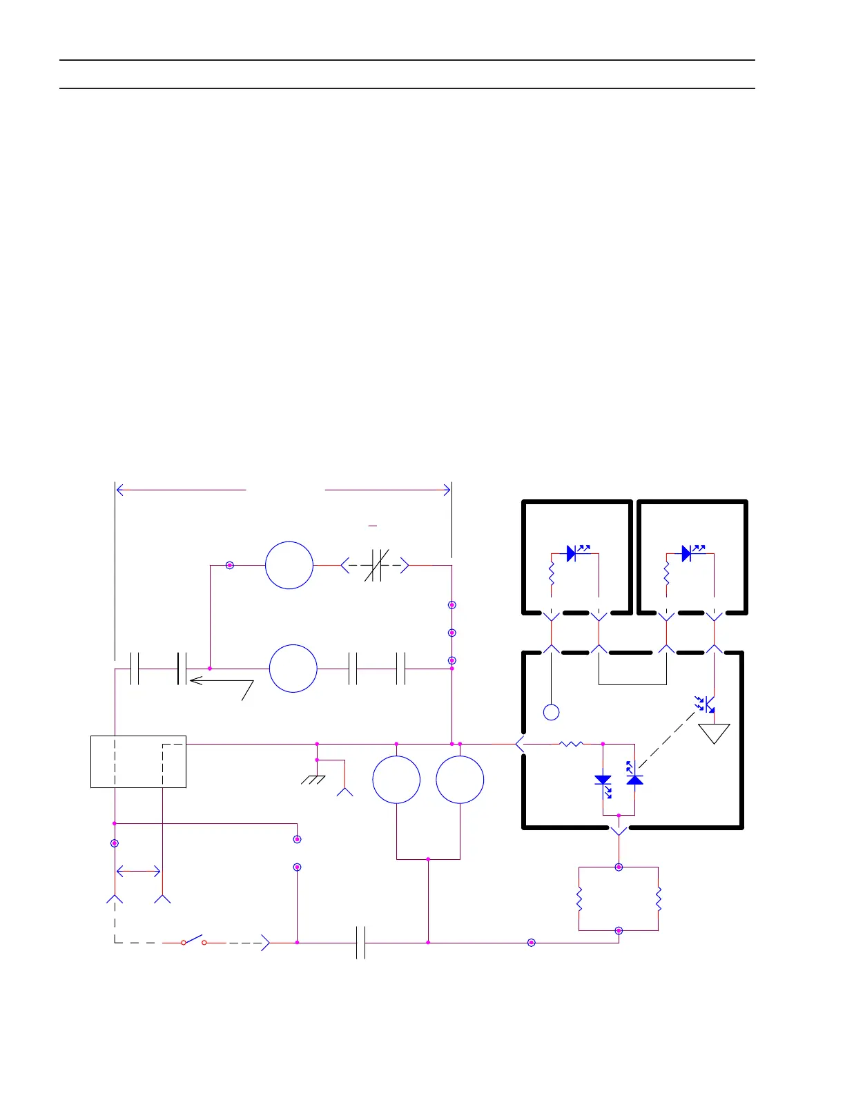
K3andK33,activatedbysupplyingaContactorSignal,initiateandcontrolstheoperationofK2(StartingContactor)and
K4 (Pilot Arc Contactor). K3/K33 are called the Auxiliary Main Contactors because they must be activated before the
MainContactor(K1)power-upsequencecanoccur.TheContactorSignalissuppliedthrougharemotecontactconnect-
ing115VACfromJ1-RtoJ1-M.IfK6isclosed(nofault),K3willactivate.TheclosingofK3(6,9)activatesK2,theStarting
Contactor,andK4,thePilotArcContactor,providedthepowersourceisnotoverheated.SeeSubsection6.7,E-stopand
MainContactorCircuitsformoreinformationontheoperationofK2.K4isturnedowhentheCurrentDetectorsensesarc
currentandopensthecontactconnectingP2-5toP2-6ontheControlPCBoard.
InadditiontooperatingK3/K33,theContactorSignalalsoactivatestheSolidStateContactor.TheSolidStateContactoris
alogicandinterlockcircuitpermittingtheIGBT’stoconductwhenevertheremoteContactorSignalispresent.The115V
ACContactorSignalisfedtoTB1-9,TB7-8,andresistorsR45andR45A.Theseresistorsreducethe115Vtoapproximately
16VACfedintotheControlPCBoardatP6-1andP6-2.TheControlPCBoardsendsasignaltoboththeLeftandRightPWM
/GateDrivePCBoards.IlluminationofLED3onbothofthePWM/GateDrivePCBoardsisindicationthattheSolidState
Contactorisfunctioning.
6.6 Auxiliary Main Contactor (K3 & K33) and Solid State Contactor Circuits
K33 K15
6 69
R45B
TB7-8
TB7-9
P6-1
TB1-9
K3
K2
K4
P2-5 P2-6
TB1-7
K33
J1-Z
TB9-16
TB9-13
TB9-18
P1-9 P1-10
680
P6-2
K3 K7
6 699
ON/OFF
IGBT DRIVE
ON/OFF
LED3 LED3
LEFT PWM/GATE
DRIVE PC BOARD
RIGHT PWM/GATE
DRIVE PC BOARD
+15V
CONTROL
PC BOARD
Solid State Contactor
T
(AMC)
K6
96
NEUTRAL
HOT
I
N
FN4
J1-R
J1-M
115V
4
12
AC
STARTING
CONTACTOR
PILOT ARC
CONTACTOR
3
H
Current Detector
Contact on
Control PCB
Fault Relay
115V AC
IGBT DRIVE
J1-H
AUXILLARY MAIN CONTACTOR (K3 & K33) & SOLID STATE CONTACTOR CIRCUITS
Open with fault or
main line power off
Over Heat Relay - Closed
during normal operation
R45A
8W
10K
P1-9 P1-10
TB7-8
P10-5
P10-6
P11-5
P11-6
8W
10K
TB8-7
TB1-8
CONTACTOR SIGNALCONTACTOR SIGNAL