TABLE OF CONTENTS
0463 691 001 © ESAB AB 2019
1
SAFETY ....................................................................................................... 4
1.1 Meaning of symbols ............................................................................... 4
1.2 California Proposition 65 Warning........................................................ 4
1.3 Safety precautions ................................................................................. 4
1.4 User responsibility ................................................................................. 8
2
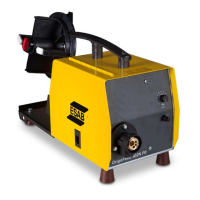
INTRODUCTION.......................................................................................... 12
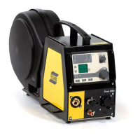
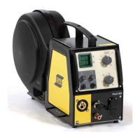
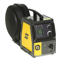
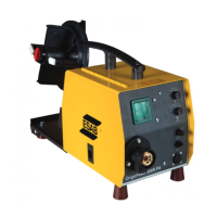
2.1 Equipment ............................................................................................... 12
3
TECHNICAL DATA ...................................................................................... 13
4
INSTALLATION............................................................................................ 15
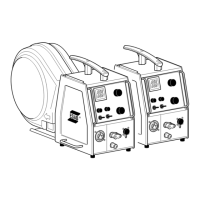
4.1 Lifting instructions ................................................................................. 15
5
OPERATION ................................................................................................ 17
5.1 Recommended maximum current values for connection cables set 18
5.2 Connections and control devices ......................................................... 19
5.3 Cooling liquid connection ..................................................................... 19
5.4 Retrofitting an interconnection strain relief kit ................................... 20
5.5 Heat kit switch (Offshore versions only).............................................. 22
5.6 Starting procedure ................................................................................. 22
5.7 Lighting inside the wire feed unit ......................................................... 22
5.8 Bobbin brake........................................................................................... 22
5.9 Changing and loading wire.................................................................... 23
5.10 Changing feed rollers............................................................................. 23
5.11 Changing the wire guides...................................................................... 24
5.11.1 Inlet wire guide ..................................................................................... 24
5.11.2 Middle wire guide ................................................................................. 25
5.11.3 Outlet wire guide .................................................................................. 25
5.12 Roller pressure ....................................................................................... 25
5.13 Wear parts storage compartment ......................................................... 27
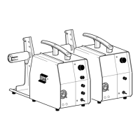
5.14 Attaching the wheel kit .......................................................................... 27
5.14.1 Attaching the wheels to the wheel kit frame ......................................... 27
5.14.2 Wire feed unit in vertical position.......................................................... 28
5.14.3 Wire feed unit in horizontal position ..................................................... 28
5.15 Attaching both the wheel kit and the torch strain relief accessory... 29
6
CONTROL PANEL....................................................................................... 31
6.1 Pro............................................................................................................ 31
6.1.1 External control panel........................................................................... 31
6.1.2 Internal control panel............................................................................ 32
6.2 Setting the speed unit of measurement (metric/imperial) .................. 32
6.3 Explanation of functions........................................................................ 33
6.4 Overtemperature indicator .................................................................... 34
6.5 Measured values .................................................................................... 34
6.6 Setting the gas flow................................................................................ 35