CUTMASTER 40
0-5557 INTRODUCTION
17
2.05 Input Wiring Specications CSA
1 Phase Input Cable Wiring Requirements
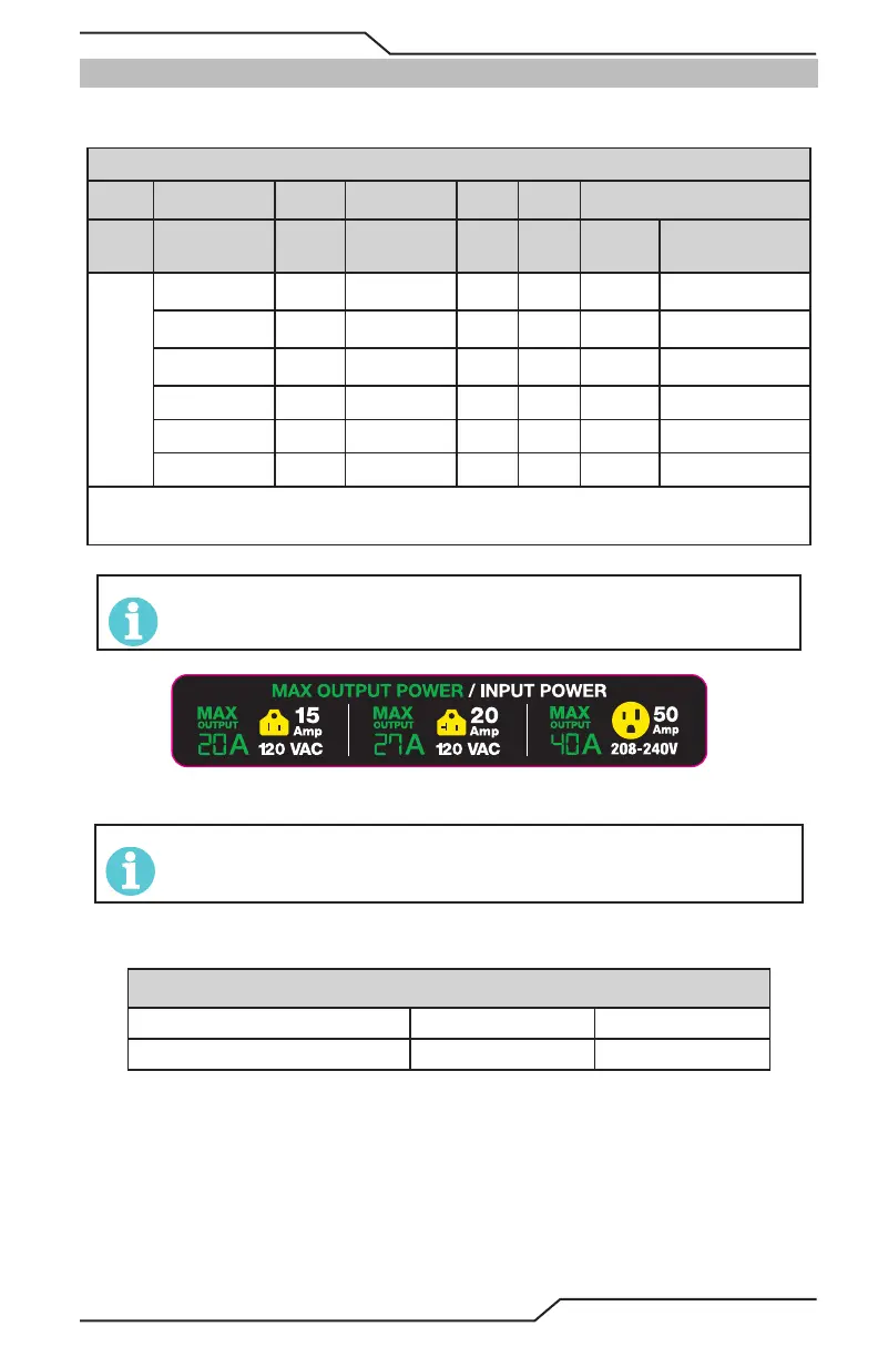
1 Phase CutMaster 40 Power Supply Input Cable Wiring Requirements
Input voltage Freq Power Input Suggested Sizes
Volts Hz kVA I max I
1
e
Fuse
(amps)
Flexible Cord
(Min. AWG)
1 Phase
120 / 15A 50/60 2.3 19.3 13.6 15 12 AWG
120 / 20A 50/60 3.1 25.3 18.3 20 12 AWG
208 50/60 6.1 29.2 18.5 50 12 AWG
220 50/60 6.1 27.9 17.6 50 12 AWG
230 50/60 6.0 26.1 16.5 50 12 AWG
240 50/60 6.0 25.1 15.9 50 12 AWG
Line Voltages with Suggested Circuit Protection and Wire Sizes
Based on National Electric Code and Canadian Electric Code
NOTE!
Refer to Local and National Codes or local authority having jurisdiction for proper wiring requirements.
Cable size is de-rated based on the Duty Cycle of the equipment.
Art# A-14359
NOTE!
Due to circuitry, age and condition two generators with the same ratings may produce dierent results. Adjust the
amperage accordingly.
CM 40 Cut Capacity
Recommended Pierce Maximum
1/2" (12.7mm) 1/2" (12.7mm) 1" (25.4mm)