Do you have a question about the Esaote O-scan Series and is the answer not in the manual?
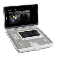
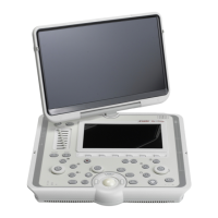
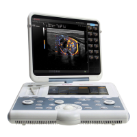
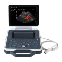
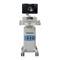
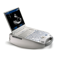
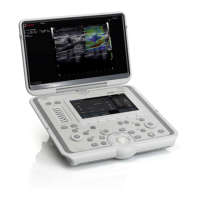
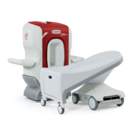
Describes the O-scan MR system, its main parts: patient seat, console, magnetic unit, and electronic box.
Details the O-scan system's purpose for imaging limbs and joints, specifying areas and technical parameters.
Lists conditions and patient types for which O-scan MR system use is contraindicated.
Outlines safety measures for controlled access areas and general precautions for system use.
Highlights special precautions required for MR examinations involving newborns, infants, and pregnant women.
Provides guidance on preserving O-scan system performance and image quality through proper maintenance.
Defines the operator's qualifications, training, and physical requirements for safe system use.
Specifies the intended actual conditions and settings for users interacting with the O-scan medical device.
Details the definition and importance of a controlled access area around the O-scan system for safety.
Outlines requirements for peripheral equipment used within the controlled access area, emphasizing MR safety.
Warns about ferromagnetic objects being attracted by the magnetic field, posing a projectile risk.
Explains causes of image artifacts, including magnetic field disturbances and shielding element efficiency.
Describes the susceptibility test protocol to assess O-scan system compatibility with peripheral equipment.
Defines the patient area where intentional/unintentional contact can occur, ensuring safety levels.
Emphasizes careful evaluation of patient risks, history, and contraindications before examinations.
Details precautions for patients with metal implants, emphasizing MR Conditional assessment.
Highlights special precautions for MR examinations involving pregnant women and newborn babies.
Outlines special precautions for patients with high risks like cardiac arrest, seizures, or claustrophobia.
Stresses the importance of maintaining patient communication and monitoring well-being during examinations.
Requires evaluation of risks associated with MR personnel's history and tasks before entering the controlled access area.
Defines emergency procedures to assist patients during MR examinations, including patient removal from fields.
Specifies the O-scan system's operating mode as Normal Operating Mode according to EN 60601-2-33 standards.
Addresses acoustic noise levels generated by the O-scan system and necessary precautions.
Recommends ear protection for sedated patients or in high noise environments to prevent hearing impairment.
Discusses safety issues related to static magnetic fields, biological effects, projectile effects, and implanted devices.
Illustrates magnetic fringe field maps on different planes and describes field isolines.
Details positions of maximum magnetic field and gradient, and their spatial coordinates relative to the magnet isocenter.
Explains induced electric fields from time-varying magnetic fields and potential stimulation of body systems.
Addresses field intensity increase towards gantry side walls and precautions for knee examinations.
Discusses exposure levels for MR workers to electric fields and relevant regulations.
Covers heating as a consequence of RF exposure and SAR comparison with induced heat.
Explains contact current generation and O-scan system conformance to directives and standards.
Details risks of localized heating due to closed conductive loops formed by patient contact with coils or cables.
Highlights dimensional restrictions and patient comfort considerations for safe and effective positioning.
Addresses mechanical stability and precautions for patient seat, leg rest, and padded lateral supports.
Stresses that installation, maintenance, and repair must be done by authorized personnel.
Provides precautions regarding cleaning agents, flammable substances, and appropriate fire extinguishers.
Details precautions for using paramagnetic contrast agents, including manufacturer labeling and potential adverse effects.
Outlines procedures for disinfecting and cleaning the O-scan system after contact with infected materials.
Lists periodic maintenance procedures to be performed by authorized service personnel and their frequency.
Describes the image quality test implemented to measure Signal-to-Noise ratio and verify image quality stability.
Explains the automatic shimming test for evaluating and correcting magnet homogeneity.
Specifies the system's lifetime guarantee and maintainability period from the date of purchase.
Emphasizes the critical nature of patient data modifications and the responsibility for conserving CSV files.
Confirms O-scan compliance with Medical Equipment Directive 93/42/EEC and various EN standards.
Specifies minimum clearances and floor load capacity requirements for O-scan system installation.
Details EMC requirements, including LAN connection specifications and warnings about incompatible cables.
Provides declarations on RF and harmonic emissions compliance and guidance for electromagnetic environments.
Details immunity test levels and compliance for ESD, electrical fast transients, surge, voltage dips, and power frequency fields.
Recommends maintaining minimum distances from RF systems to prevent interference with the MRI system.
Advises against installing the system near large ferrous masses or equipment causing magnetic field fluctuations.
Warns against installing near devices with frequent activation/shutdown or in areas with voltage fluctuations.
Outlines system power supply, consumption, grounding, and connection specifications for electrical mains.
Describes the function of green and blue indicator lights on the electronic cabinet and PC.
Illustrates and defines common safety symbols used on the O-scan system equipment.
Explains the need for constant magnet temperature and the function of the thermostat control circuit.
Specifies ambient temperature, humidity, and other environmental conditions for optimal system operation.
Details system modularity, positioning flexibility, and cable routing requirements for installation.
Recommends audio and visual contact between physician and patient during examinations.
States that installation must be carried out by authorized technical assistance personnel.
Details the definition and importance of a controlled access area around the O-scan system for safety.
Instructs on affixing warning and prohibition labels and marking the 0.5 mT line on the floor.
Specifies temperature, pressure, humidity, and exposure time limits for O-scan system transport and storage.
Outlines measures for handling the magnetic unit during transport due to fringe field presence.
Describes symbols found on shipping crates warning of magnetic fields and handling precautions.
Highlights key features: ultra-compact magnet, integrated Faraday cage, self-centering mechanism, and specialized devices.
Describes the O-scan system's electrical medical device components and accessories.
Lists additional items such as operator table, magnetic compensation kit, and E-MRI viewer.
Details the PC, including keyboard, mouse, and SDSP card, and monitor specifications.
Explains the console as the instrument for operator interaction, covering PC, monitor, keyboard, and mouse.
Provides detailed specifications for the system's LCD/TFT/LED monitor, including resolution and connectors.
Describes the electronic components housed in the electronic box, including power supply and PC details.
Details the components of the power supply system: TRI transformer and DISTR unit.
Describes the PC and SDSP card, outlining their functions for signal acquisition and monitoring.
Details the functions of the ACM, TCM, SRN, and RISC cards within the electronic box.
Explains the GRA's role in supplying voltage/current to gradient coils and its CGM card functions.
Describes the RF amplifier's capability to supply transmission coils with power for faster pulse sequences.
Lists the HEATER card and DIM card used for connecting the electronic cabinet and displaying real-time images.
Summarizes the processes controlled by the computer, including user dialogue, malfunction control, and data management.
Details the components of the magnetic unit: magnet, gradient coils, RF transmission coil, RF screen, receiving coils, and thermal control.
Lists technical specifications for the imaging system, acquisition methods, slice thickness, and spatial resolution.
Details the patient seat's design for comfort, including its padded bed, castor wheels, track, and handle.
Describes the patient seat's features in eXP and Premium configurations, including adjustable armrests for patient positioning.
Introduces two padded supports applied to the magnetic unit for examining knees, calves, ankles, or feet.
Explains the device for knee cinematic studies, its ability to maintain position, and generate stress conditions.
Provides step-by-step instructions for using the cinematic knee device, including knob operations and adjustments.
Outlines steps to prepare the cinematic knee device before inserting the patient's limb into the gantry.
Details the steps required to remove the patient's limb and return the cinematic knee device to its original state.
Explains how to perform cinematic studies of the knee by acquiring consecutive images at different bending angles.
Guides the user through using the patient seat and devices for cinematic studies, referencing relevant chapters.
Introduces the hand/wrist positioner, its components, and its purpose in stabilizing limbs for examinations.
Details the components of the hand/wrist positioner: support, positioning plate, cushions, and straps.
Explains the two types of supports used with the hand/wrist positioner, depending on the coil.
Describes how to fix the positioning plate guide to the base and adjust the plate using a knob and graduated scale.
Explains the placement of cushions and pins on the positioning plate to ensure patient comfort and limb stability.
Describes shielding collars as conductive fabric cylinders for limb shielding and their connection to the gantry.
Provides steps for performing a periodic inspection of shielding collar integrity using a phantom and specific commands.
Explains the use of aluminum straps to improve electrical contact between the patient's skin and shielding straps.
Details the fabric insulating strap used to prevent thigh contact with the gantry, essential for O-scan operation.
Provides instructions for cleaning, replacing, and disposing of shielding covers and straps according to regulations.
Introduces Dual Phased Array coils, their structure, and benefits over solenoidal coils for signal-to-noise ratio.
Details the DPA Knee Coil 1, its dimensions, base engagement, quick connector, and use with rectangular cushions.
Describes the Hand/Wrist DPA Coil 2, its dimensions, gantry engagement, connector, and use with rectangular cushions.
Details the Foot/Ankle DPA Coil 3, its shoe-like shape, dimensions, gantry engagement, connector, and use with special cushions.
Highlights precautions for handling receiving coils, including avoiding shocks, careful insertion, and cleaning procedures.
Describes various phantoms used for system tuning, quality tests, and magnetic compensation analysis.
Lists all items in the Soft Cushion Set and their corresponding O-scan system parts.
Identifies the cushions for the patient seat: backrest cushion and headrest.
Explains the function of the cushions holder for Knee Coil 1 in correctly positioning the knee.
Describes the lumbar support cushion placed between the seat and patient's back to improve comfort, especially for hand/wrist/elbow exams.
Provides general notes on cushion compressibility, selection, placement, and stacking for optimal patient positioning and image quality.
Details gantry opening dimensions and distance from entrance point to magnet center affecting examination possibilities.
Emphasizes positioning the coil and anatomical region in the center for optimal image quality and Scout sequence verification.
Provides recommendations for optimal image quality, including coil selection, limb immobilization, and use of shielding.
Outlines the step-by-step procedure for quickly removing a patient from the unit in an emergency situation.
Identifies Knee coil 1 (DPA) as the usable coil for knee examinations.
Specifies the use of rectangular cushion types P and insulating straps for correct knee examination positioning.
Provides detailed steps for positioning the patient for knee examinations, including seat adjustment, shielding collars, and coil insertion.
Explains how to perform cinematic studies of the knee by acquiring consecutive images at different bending angles.
Details the procedure for examining cruciate ligaments and the femor-rotula joint using the knee examination protocol.
Identifies DPA Knee coil 1 as the usable coil for calf examinations.
Specifies the use of rectangular cushion types P and insulating straps for correct calf examination positioning.
Provides steps for positioning the patient for calf examinations, including seat adjustment, shielding collars, and coil insertion.
Identifies DPA Knee Coil 3 and DPA Knee coil 1 for foot-ankle examinations based on patient size.
Lists required cushions (SC1, SC1+SC2, P, C) for correct patient positioning in foot-ankle examinations.
Details the patient positioning procedure for ankle examinations using DPA Foot/Ankle Coil 3 or DPA Knee Coil 1.
Provides steps for positioning the patient for forefoot examinations, including seat and cushion placement.
Outlines the patient positioning procedure for Achilles' tendon examinations, considering large feet and seat adjustments.
Identifies DPA Hand/Wrist Coil 2 and DPA Foot/Ankle Coil 3 as usable coils for hand-wrist examinations.
Lists required cushions (rectangular types P, RB Cushion, Lumbar support cushion) for hand-wrist examinations.
Details the procedure for positioning the patient's hand for examinations using DPA Hand/Wrist Coil 2 or DPA Foot/Ankle Coil 3.
Provides steps for positioning the patient's wrist for examinations, including coil insertion and cushion placement.
Identifies DPA Hand/Wrist Coil 2 and Foot/Ankle Coil 3 for elbow examinations based on patient size.
Lists required cushions (rectangular types P, Lumbar support cushion) for elbow examination positioning.
Details the procedure for elbow examinations, including coil insertion, cushion placement, and shielding collar use.
Identifies DPA Hand/Wrist coil 2 and Foot/Ankle Coil 3 for forearm examinations based on patient size.
Lists required cushions (rectangular types P, Lumbar support cushion) for forearm examination positioning.
Provides steps for forearm examinations, including coil insertion, cushion placement, and shielding collar use.
Describes the procedure to start up the O-scan system, including PC and system electronics power-on.
Details steps for closing the user interface, disconnecting the user, and shutting down the system completely.
Explains how to block RF impulses and magnetic field generation in emergency situations via software or main switch.
Describes the control panel's location and function for real-time acquisition management on the O-scan system.
Enables image acquisition every 2 seconds for facilitating anatomical region positioning via the control panel.
Explains setting the control panel in standard or inclined positions to aid patient positioning and supervision.
Details how to enable the control panel via the user interface and its power management during scans.
Explains the quantum mechanical property of spin in atomic nuclei and its relation to magnetic moment.
Describes how RF pulses disturb proton alignment, causing resonance and transverse magnetization, generating the MR signal.
Explains T1 and T2 relaxation times and their importance in identifying tissue characteristics and signal source.
Details how RF pulses create transverse magnetization and FID signals, and how relaxation times are measured to form images.
| Gantry Design | Open |
|---|---|
| Magnetic Field Strength | 0.25 T |
| Magnet Type | Permanent |
| Scan Region | Extremities |
| Field Strength | 0.25 T |