Handset 1 Handset 1
Red
Black
Red
Black
White
Purple
5
4 Core
240 AC
2 Core 2 Core
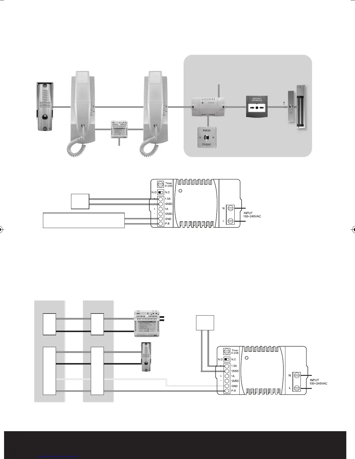
Additional accessories required for door control
240V AC
2 Core 2 Core
EV-BPS
EV-EXIT
EV-EBG
EV-ML250
Evoke Call Point System Wiring
Evoke Handset(s) with Call Point
EVBPS wiring
P2
240V AC
Lock selector switch
N.O = Yale
N.C = Mag Lock
P1
Evoke Handset to Evoke Call Point Wiring
Evoke Handset with Evoke Call Point
2 Core2 Core
2 Core
1
2
3
4
5
6
LOCK
Lock selector switch
N.O = Yale
N.C = Mag Lock
1
2
3
4
5
6
LOCK
From Handset +
Push to Exit Button - EVEXIT
P2
P1
Red
Black
Red
Black
White
Purple
Evoke Manual_Layout 2 24/07/2012 10:11 Page 5