MAG816 - Installation and Operation Manual 11
3.6
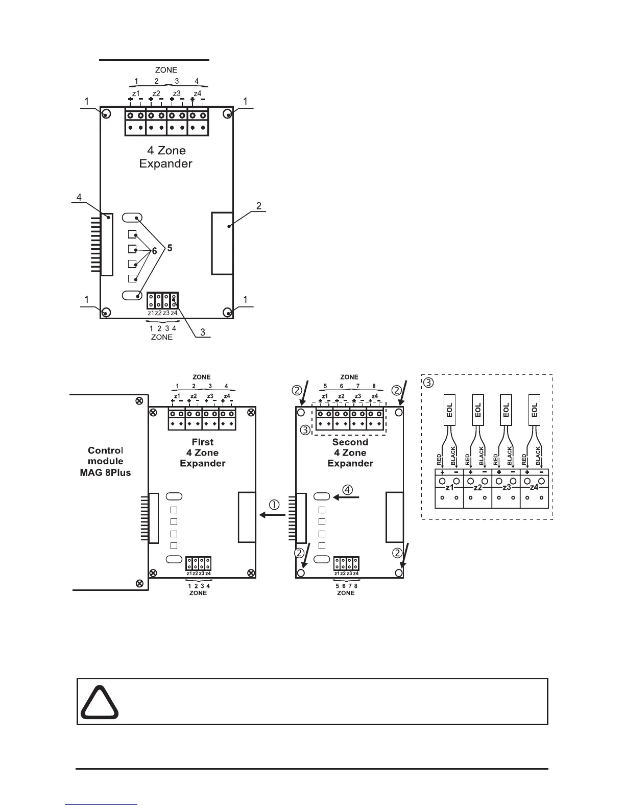
4-Zone Expander
• 1 - Mounting holes for xing the expander to the
chassis.
• 2 - Connector for connecting of additional
4-zone / 4-sounder expander.
• 3 - Jumpers for Instant action mode
programming.
Example: To program ZONE1 in Instant action
mode set a jumper on the z1 position.
• 4 - Connector for connecting:
а) To the control module, when the 4-zone
expander is the rst module in the panel
conguration.
b) To a previous 4-zone expander;
• 5 - Mounting holes for placing a lightpipe for the
front panel LED indication, see Position 11 of the
additional components included, page 31.
• 6 - LEDs Zone status indication.
Connecting of Additional 4-Zone Expander
• 1 - Connect the connectors of the expanders.
• 2 - Fix the second 4-zone expander with screws from the spare parts kit
(position 10, page 31) to the metal box frame.
• 3 - Mount the EOL-modules from the supplied spare parts kit (position 12,
page 31) to the zone expander’s terminals as observe the polarity.
• 4 - Place the lightpipe (Position 11, page 31).
ATTENTION: Do not connect or disconnect the expander when the power
is on! Before connecting or disconnecting the expander you SHOULD
check whether the main and the stand-by power supplies are OFF!
The metal box of MAG816 can accommodate up to 4 zone expanders. To each zone
can be connected up to 32 conventional detectors with consumption <200µA at normal
operation mode and unlimited number of manual call points.