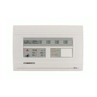
MAG816 - Installation and Operation Manual 27
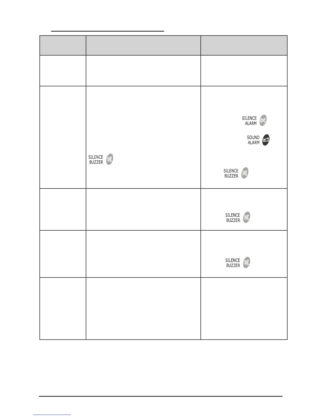
7.2 Indication of the Operation Modes
Operation
Mode
LED Indication Sound Signalization
Normal
Mode
The POWER SUPPLY 230V green
LED lights on the front panel.
-
FIRE
A FIRE relay is
activated.
• The two red FIRE LEDs light up si-
multaneously - the FIRE LED and the
zone/zones LED (also in red) where the
alarm occurred.
• The LEDs will remain lit even after the
button has been pressed.
• The sounders are activated.
They can be disabled by
pressing the
but-
ton and can then be enabled
by pressing the
.
• The internal buzzer is acti-
vated. It is disabled by press-
ing the
button.
FAULT
A FAULT relay
is activated.
• The GENERAL FAULT yellow LED
and the fault LED according to the Ta-
ble in item 7.1 light up simultaneously.
• The internal buzzer is acti-
vated. It is disabled by press-
ing the
button.
TEST
Tests the sys-
tem for proper
operational
efciency
• The two yellow LEDs blink simultane-
ously - the TEST LED and the zone
LED (also in yellow, 2 blinks per sec-
ond) where the test is conducted.
• The internal buzzer is acti-
vated. It is disabled by press-
ing the
button.
DISABLE
Disabled
zones and/or
sounders.
• The ENABLE/DISABLE yellow LED
is lit on.
• The respective zone LEDs light up in
yellow to indicate disabled zones.
• The yellow SOUNDER FAULT/DISA-
BLE LED lights up to indicate disabled
sounders.
-