MAG816 - Installation and Operation Manual 9
3.4 Control Module
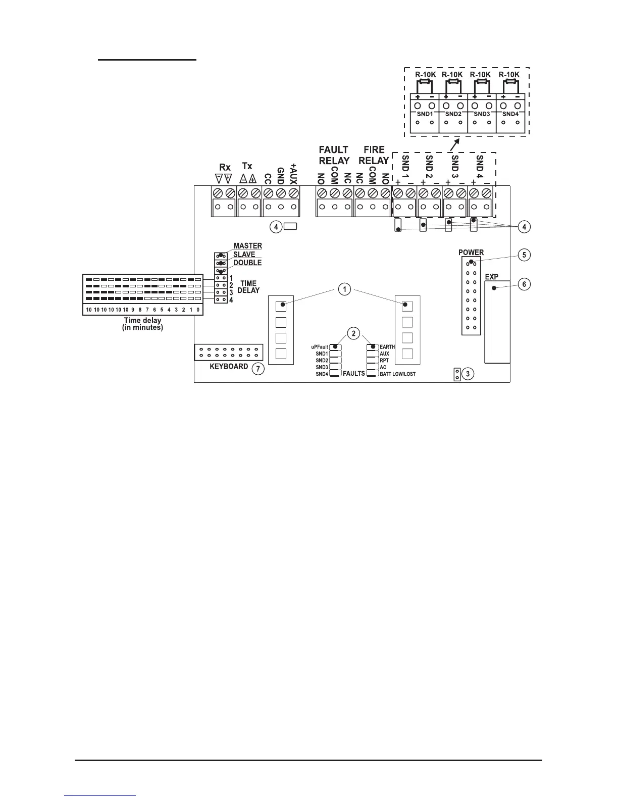
Figure 10.
• Rx/Tx - Terminals for connecting of Repeater, Relay Module or a combined connection
between them (see items 4.1 and 4.2);
• CC (Class change) - Terminal for connecting of a switch (see item 4.3);
• GND - Grounding;
• +AUX - Auxiliary output, +24V DC / 0,3A;
• FAULT RELAY - Fault Relay, +12V / 1A or +24V / 0,5A;
• FIRE RELAY - Fire Relay, +12V / 1A or +24V / 0,5A;
• SND 1 ÷ SND 4 - Sounder outputs, +24V / 0,3A; Mount the resistors R-10K from the
supplied spare parts kit (position 1, page 31) to the sounder terminals;
• DOUBLE - Double Action Mode (see item 5.2);
• MASTER - Master Panel Mode (see item 5.4);
• SLAVE - Repeater Panel Mode (see item 5.5);
• TIME DELAY - Sounder Delay Programming.
- LED Indication of the operation modes, lightpipe mounted (Position 7, page 31);
- Faults LED indication, see item 7.1;
- Jumper for enable/disable Earth Fault Indication;
- Resettable (PTC) fuses;
- Connector for connecting the main power source;
- Connector for connecting 4-zone / 4-sounder expander;
- Connector for connecting the control panel keypad.
Table for Sounder
Delay Programming
(in minutes).
MAG816