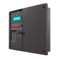
The MAGDUO is an intelligent 2-wire fire detection and alarm system control panel. It utilizes a conventional cabling format, classifying it as an 'Analogue non-addressable' system. All field devices, including sounders, connect to the zone via a common 2-core screened cable, communicating with the control panel using the 'MAGDUO' data protocol. The panel monitors each zone for detector head removal, device faults, 'End of line' faults, and open or short circuit faults.
Function Description:
The MAGDUO control panel provides comprehensive fire detection and alarm system management. It offers two monitored outputs configurable as conventional sounder circuits or 24V monitored relay circuits, a volt-free common fire relay, and a volt-free common fault relay. Additionally, it includes two multifunction latching/non-latching inputs and one monitored input programmable with options like 'Class-Change' and 'Remote fire input'. The system supports 'Alarm Confirmation' technology, primarily designed to address unwanted alarms in apartment blocks or 'Houses of Multiple Occupancy' (HMOs). This feature allows certain detector alarms to be checked or confirmed before activating the entire system. A local or zonal 'Alarm Confirmation Warning' sound is given, allowing occupants to check for a possible fire. If the cause of the alarm is removed, the warning ceases, and the system returns to normal. If the alarm persists, the system enters a full alarm state. Manual Call Points always trigger an immediate alarm, regardless of zone type.
Important Technical Specifications:
- Dimensions: 331 x 331 x 99 mm
- Weight (excluding batteries): 2.25 kg (2 Zone), 2.28 kg (4 Zone), 2.36 kg (8 Zone)
- Construction: VO rated ABS
- IP Rating: IP 30
- Cable Entry: 13 x 20mm knockouts, 1 x 50mm x 50mm pull out tab
- Cable Type: 2-core 1.5mm² screened fire rated cable (e.g., FP200, Firetuff, Firecell, Lifeline or equivalent)
- Maximum Cable Length per Zone: 500m
- Detection Zones: 2 Max (2 Zone Panel), 4 Max (4 Zone Panel), 8 Max (8 Zone Panel)
- Devices per Zone: Up to 32 devices, dependent on Device Loading Units (DLUs) not exceeding maximum loading. Conventional zones support a maximum of 20 devices per zone.
- Device Protocol: MAGDUO
- Monitored Sounder Circuits: Up to 2
- Monitored Relay Circuits: Up to 2
- Relays on Board: Common fire and common fault
- Operating Standard: BS EN54-2 & 4
- Operating Temperature: 5°C to 40°C
- Mains Voltage: 230V AC Nominal 700mA
- PSU Output (4 hour continuous): 2.1A
- Operating Voltage: Nominal 24V DC (Range 21-31V DC)
- Battery Charger Output: 300mA Max
- Battery Voltage (During Charge): 27.3 V DC @ 20°C
- Internal Battery Capacity: 2 x 12V 3.2Ah (or 3.3Ah) for up to 48-hour standby. For 72-hour standby, an external battery box (2 x 12V 7Ah batteries) is required.
- Maximum Internal Resistance (including connections and Fuse): 1.3R
- Zone Output (max): 160 mA
- MAGDUO Zone Voltage (nominal): 30V DC
- Conventional Zone Voltage (nominal): 20V DC
- Monitored Outputs 1 and 2 (max, fused): 300 mA trip polyfuse
- Monitored Outputs 1 and 2 EOL: 10k
- Monitored Outputs 1 and 2 DC Supply Current (max): 250 mA (2-4 zone panel), 200mA (8 zone panel)
- Auxiliary DC Supply Current (max): 250 mA
- Auxiliary DC Supply Volts (Unregulated): 21V – 31V DC
- Common Fire Relay: Volt free SPCO contacts 1A 30V max
- Common Fault Relay: Volt free SPCO contacts 1A 30V max
- Loading: 160 DLUs max per zone
- Zone Imin (Required by EN54-4): 30mA @24V (2 zone), 40mA @ 24V (4 zone), 60mA @24V (8 zone)
- Imax.a (Required by EN54-4): 350mA
- Fuses: Zone output (300 mA trip polyfuse), Monitored Outputs 1 and 2 (300 mA trip polyfuse), Auxiliary 24V DC supply (300 mA trip polyfuse), Mains (T4A Time Delayed 20mm Ceramic), Battery Charger (300mA current limiter), Battery (reverse polarity) (3.15A F 20mm Glass).
Usage Features:
- Mounting: The control panel should be mounted on a flat, vertical wall at a height where indicators are easily visible, ideally at the most likely point of access for fire services. It should be in a clean, dry place, away from extreme temperatures, humidity, condensation, water ingress, high vibration, shock, and at least 2 meters from transmitting equipment.
- Power Supply: Requires a dedicated 230V AC mains supply (3 amp un-switched fused spur) and 2 x 12V 3.2Ah (or 3.4Ah) sealed lead-acid batteries connected in series for standby. An external battery box with 2 x 12V 7Ah batteries can be used for extended standby times, in which case internal batteries must be removed.
- Control Panel Interface: Features a front panel with General Indication LEDs, a Control Panel Information Window, Zonal Indication LEDs, Fire Alarm Controls, and System Controls with an Enabled Keyswitch.
- Access Levels: The menu system is divided into four access levels (Normal, User, Supervisor, Engineer) to control access to various functions. Access Level 2A (User) is enabled by the key switch or a valid code. Access Level 3B (Engineer) requires removing the right-hand cover and turning on the write enable switch.
- Menu Navigation: Context-driven, cursor-highlighted selection menu system. Navigation via UP/DOWN keys and ENTER, or by entering option numbers. ESC key exits to the previous menu.
- Test Modes: Includes options to test LCD display, LEDs, buzzer, and keyboard.
- Zone Testing: Silent Test, Audible Test, and System Test modes for detection zones, allowing for one-man walk tests.
- Enable/Disable Functions: Global disablement/enablement of fire outputs, sounders, delays, and individual detection zones.
- Time and Date Setting: Adjustable time and date, though the system does not automatically adjust for BST/Daylight saving.
- Event Logs: Stores up to 500 fire, fault, and system events, viewable by category (All Event Logs, Fire Logs, Fault Logs, Panel Event Logs).
- Zone Configuration: View/change zone status (active/switched off), zone description, and zone mode (CP/DET for original FlexiPoint or CP/SM/HT for new ASD Device).
- Alarm Confirmation Settings: Configure zone type (Communal/Dwelling), confirmation type (System/Zonal), and confirmation delay (1-5 minutes). Setting delays greater than 1 minute is outside EN54-2 scope.
- Alarm Delay Settings: Set alarm delays for zone outputs, fire relay, and monitored outputs 1 & 2 (Instant/Delayed).
- Panel Details: View/change buzzer status (ON/OFF), access codes (User, Supervisor, Engineer), software version, panel ID number, and panel description.
- Timers: Weekly Test Timer (On/Off, Day, Time) and Service Timer (weeks interval).
- Programmable Inputs/Outputs: Configure Programmable Inputs 1 & 2 and Monitored Input for various control events (Silence Alarms, Reset System, Sound Alarms, Silence Buzzer), remote fire events (Full/No Relays), technical events (Latch/Non-Latch), and disablement events (Disable Sounders, Disable Remote Fire, Disable Sounders/Remote Fire, Disable Buzzer). Monitored Outputs 1 & 2 can be configured as Remote Sounder, Remote Fire, or OFF.
- Peripheral Bus: NET A & B is an RS485 bus for ancillary equipment (repeaters, etc.). Note: Ancillary equipment connected to the network may not meet EN 54-2 requirements.
- Magnetic Door Hold Units: Recommended to use 24V DC units connected to a power supply with battery standby for normal operation during power interruptions.
Maintenance Features:
- Regular Checks: User maintenance involves checking the log for spurious faults/messages and verifying programmed functions and device operation.
- Battery Check: Power supply batteries should be checked for leaks and low voltages during regular service (not more than 12 monthly). Batteries below 21V should be recharged or replaced; below 18V, they should be replaced.
- Fault Finding: The manual provides detailed troubleshooting for intermittent and permanent zone faults, including steps to check connections, EOL components, interference, optical chambers, and wiring.
- False Alarms: Guidance on identifying and rectifying causes of false alarms, such as dirty optical chambers, incorrectly set detectors, or missing optical chambers.
- General Faults: Troubleshooting for sounder faults, remote fire output faults, power faults (mains, battery, charger), and earth faults.
- System Reset: A system reset is required after any changes are made in engineer mode for them to take effect.
- Detector Head Removal: Devices or detector heads should only be removed with the zone switched off (at access level 3) using the correct head removal tool to prevent damage.
- EOL Configuration: Every MAGDUO device has an inbuilt 'End of line' signal, configured via DIL switches. No external resistor, capacitor, or 3rd party EOL module should be used.
- Installation Checklist: Provides a staged checklist for installers and commissioning engineers to ensure proper installation, wiring, testing, and programming.
- Cable Continuity & Insulation Test Results: Forms provided to record test results for cable continuity and insulation, essential for commissioning.