MAGDUO Control Panel Engineering and Commissioning Manual
26-1649-03
EMC
This equipment when installed is subject to the EMC directive 2014/108/EC. It is also
subject to UK Statutory Instrument 2006 No. 3418.
To maintain EMC compliance, this system must be installed as defined within this manual.
Any deviation from this renders the installer liable for any EMC problems that may occur
either to the equipment or to any other equipment affected by the installation.
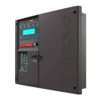
The MAGDUO System
The MAGDUO system is an intelligent ‘2-wire’ system utilising a conventional type cabling format. The
system is classed as ‘Analogue non-addressable’ due to the architecture used within the design. All
field devices including sounders can be connected to the zone via a common 2-core screened cable.
The devices communicate with the control panel using the ‘MAGDUO’ data protocol.
The MAGDUO panel monitors each zone for detector head removal, device fault, ‘End of line’ fault and
open or short circuit fault.
Devices or detector heads should not be removed with the zone switched on.
Switch off the zone (at access level 3) before removing any devices or detector
heads from that zone.
Detector heads must only be removed using the correct head removal tool.
Removing detector heads without using the correct tool will result in damage to
the head / detector base.
Every MAGDUO device has an inbuilt ‘End of line’ signal, which may be activated as required. All
setting options are configured using the DIL switches fitted to the device.
Do not use a resistor or Capacitor or any other 3
rd
party ‘End of line’ module for
‘End of line’.
The MAGDUO control panel also provides two monitored outputs that may be configured as
conventional sounder circuits or conventional 24V monitored relay circuits, a volt free common fire relay
and a volt free common fault relay. There are also two multifunction latching/non-latching inputs and
one monitored input programmable with options such as ‘Class-Change’ and ‘Remote fire input’.
The MAGDUO control panel incorporates an integral power supply unit and requires 2 x 12V 3.2Ah (or
3.3Ah) batteries to provide up to 48 hour standby times. For 72 hour standby times a separate external
battery box can be purchased which requires 2 x 12V 7Ah batteries.
All standby times depend on the system loading (refer to Technical Data for further information).
Standby battery calculations may be made using the MAGDUO Panel Battery & Loading Unit
Calculation Sheet.
Unlike most conventional fire alarm systems, which require separate pairs of cables for detector zones
and sounder circuits, the MAGDUO system requires one 2-core screened cable for each zone to
accommodate both detection devices and sounders. Furthermore, sounders are incorporated within the
detector to reduce system components and simplify installation.
The MAGDUO panels include some features described in EN54-2 as ‘optional functions with
requirements’. These are:-
Output to fire alarm devices EN54-2 Clause 7.8
Output to fire protection equipment, type A EN54-2 Clause 7.10.1
Dependency on more than one alarm signal, type A (Confirmation) EN54-2 Clause 7.12.1
Delays to outputs EN54-2 Clause 7.11.1