MAGDUO Control Panel Engineering and Commissioning Manual
26-1649-03
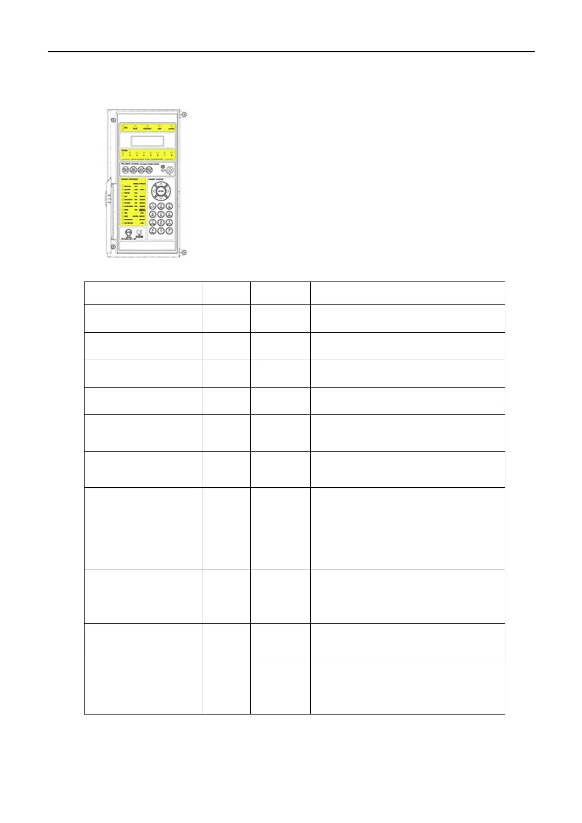
LED Indication
Note : 4 Zone / 8 Zone Panel version shown
The operation of the LED indication on the front of the control panel is
described below. The LED indication on the panel can also be
confirmed by checking the message displayed in the panel information
screen or by accessing the relevant event log from the panel menu.
The control panel is in the fire state. Other indicators
will show the origin.
The control panel is in the fault state. Other
indicators will show the origin.
This indicates that a disablement action is in place.
Enable all devices / actions to clear.
This indicates that a test routine is in place. End all
tests to clear.
This indicates that power is being supplied to the
control panel from either the 230V AC mains supply,
or the standby batteries.
A Detector or Manual Call Point in the zone indicated
is in the alarm state and sending an alarm signal to
the panel.
The system Fault LED indicates the presence of a
processor or a checksum error. Power the system
down to clear, reprogram all settings and test the
system.
This LED will also be illuminated if the ‘write protect /
write enable’ switch is left on whilst the system is not
in the engineer menu.
A mains supply fault has been detected (check for a
230V AC supply on the incoming AC terminals).
A battery fault has been detected (check batteries
and inline battery fuse).
An earth fault has been detected where a path exists
from the circuit wiring to earth. Remove circuits one
at a time to discover which one, and then rectify.
A fault condition is present on one of the zones or on
a device connected to that zone.
A device or an action associated with a zone has
been disabled.