5 P-TS7 User Manual
Inputs, Outputs, and Indicators
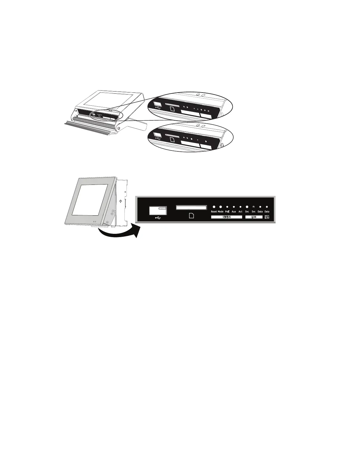
Each model of the touchscreen has an input output (I/O) panel, providing access to the USB port,
SD card slot, and a selection of indicators and service pins. Indicator and service pin selections
vary depending on the model of touchscreen.
The portable touchscreen (P-TS7-P/PE) I/O panel is located behind an access door on the bottom
of the unit.
Rese
t
Mode
Au
x
Act
Svc
Svc
D
at
a
L
ON
S
tatus
Rese
t
Mode
Aux
Act
Svc
Svc
Data
LO
N
Status
Rese
t
Mode
PoE
Act
D
ata
NET
Status
The P-TS7 wall-mount and rack-mount I/O panel is located on the bottom of the unit, viewable
only when the LCD is in its service position.
To move the touchscreen into a service position, gently pull each bottom corner of the unit
outward to a slight angle. The touchscreen rests on the pins in the mounting collar.
Ports
USB port
This connection is used for local upload and download of the configuration and theme files, as
well as firmware updates. The USB port supports all USB keys that utilize 250 mA of power or
less.
Secure Digital (SD) Card Slot
This connection is used for local upload and download of the configuration and theme files, as
well as firmware updates. The SD card slot supports standard SD media up to 2 GB.
 Loading...