Operating Instructions Safety Systems
MGB-L0…-AR.-… and MGB-L0…-AP.-…
26
(translation of the original operating instructions) 112657-12-01/15
11.8. Terminal assignment and contact description
Power
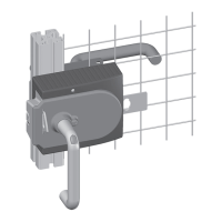
LEDs
State
DIA
GN
GN
RD
Figure 15: Connections and indicator LED
Terminal Designation Description
X3.1 to X3.3 - See the enclosed data sheet
X3.4 UA Power supply for monitoring outputs and cover assembly, DC24V, must be permanently present.
X3.5 0V Ground, DC0V (connected internally to X5.5).
X3.6 - Not used
X3.7 - Not used
X3.8 - Not used
X4.1 FI1A In case of AR conguration: Enable input for channel A, connect to DC24V in separate operation. In case of switch chains, con-
nect output signal FO1A from previous device.
In case of AP conguration: Input is not evaluated.
X4.2 FI1B In case of AR conguration: Enable input for channel B, connect to DC24V in separate operation. In case of switch chains, con-
nect output signal FO1B from previous device.
In case of AP conguration: Input is not evaluated.
X4.3 - See the enclosed data sheet
X4.4 FO1A Safety output channel A, ON when door is closed and bolt tongue is retracted.
X4.5 FO1B Safety output channel B, ON when door is closed and bolt tongue is retracted.
X4.6 RST Reset input, device is reset if DC24V is applied to RST for at least 3 s.
X5.1 OD Door monitoring output,
ON when the door is closed.
X5.2 OT Bolt tongue monitoring output,
ON when the door is closed and the bolt tongue is inserted in the interlocking module.
X5.3 - Not used
X5.4 OI Diagnostics monitoring output,
ON when the device is in the fault state.
X5.5 0V Ground, DC0V
(connected internally to X3.5).
X5.6 UB Power supply, DC24V
X2.1 to X2.8 - See the enclosed data sheet
X1 - Reserved for connection of the cover circuit board (only for populated covers)
Table 2: Terminal assignment and contact description
 Loading...