EUROMAG | MC608 | Ed. 10/2018
MC608 INSTALLATION 4
4.3 ELECTRICAL CONNECTION
In order to properly connect electrical elements of the MC608 converter to the power supply, and
to the junction box (in REMOTE version), please refer to the wiring diagram shown in paragraph
4.3.1 (Fig. 23).
The use of cables not supplied or certied by Euromag International may jeopardize the correct
functioning of the system, and it will void the warranty.
All interventions on electrical connections must be performed only when the device is
disconnected from the mains and/or battery.
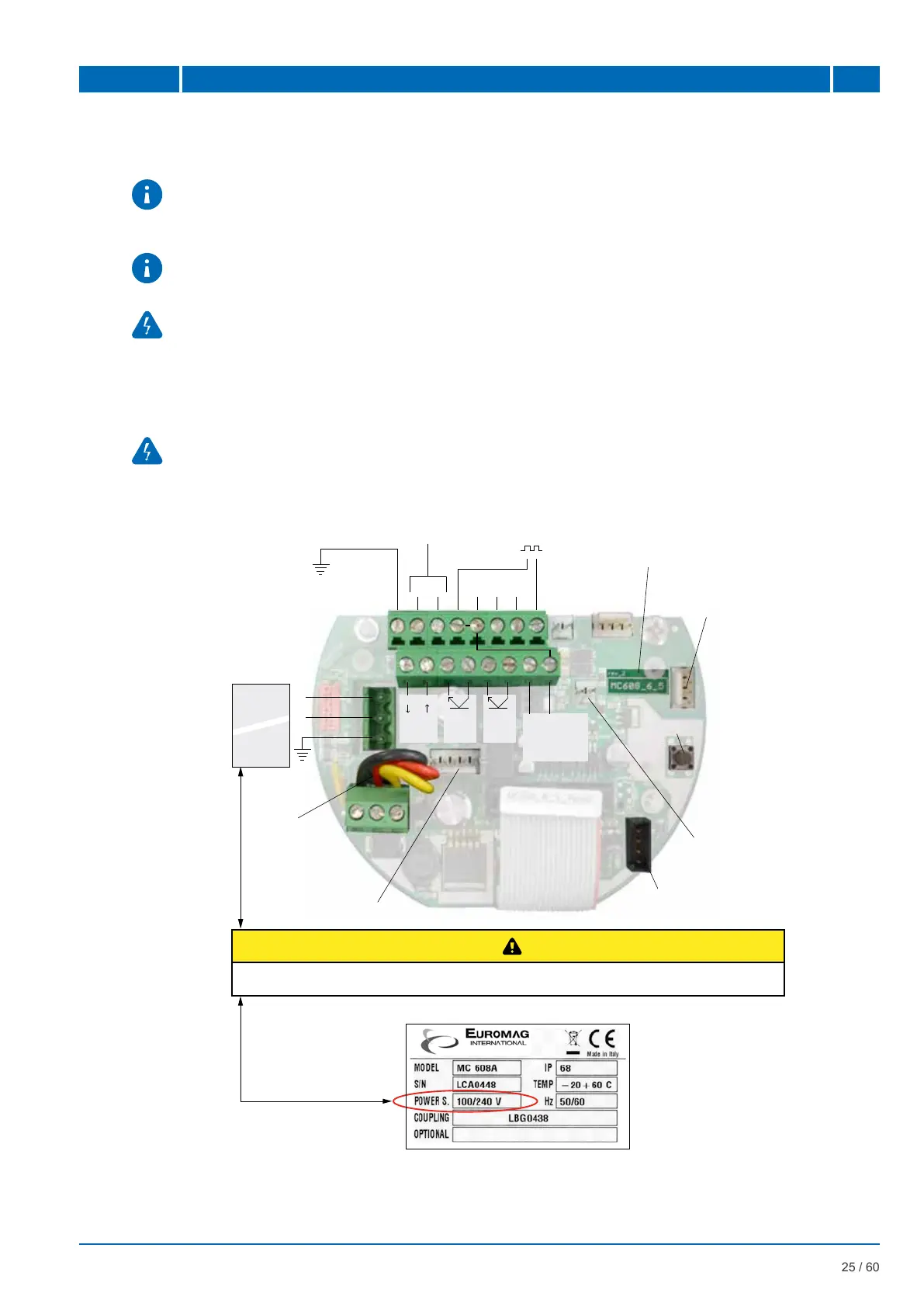
4.3.1 Wiring diagram
All interventions carried out on the electrical junction box or electrical components must be
performed by properly trained specialized personnel.
HARDWARE
VERSION
RESET
SENSOR
COILS
ELECTRODES
GROUNDING
PROGRAMMABLE
INPUT
+ -
RS485
GND A B
FREQUENCY
OUTPUT
-
+
PROG
OUT
PULSE
OUT
+ -
4-20mA
24VDC OUT
MAX 30mA
N
L
HV 100-240
VAC
50/60Hz
LV
12/24
VAC/DC
INTERNAL
POWER
SUPPLY WIRES
CHECK THE POWER SUPPLY OF THE PLATE PROVIDED
HV 100-240VAC 50/60Hz LV 12/24 VAC/DC
1 2 3 4 5 6 7 8
9 10 11 12 13
14 15 16
BATTERY PACK CONNECTOR
CONNECTOR FOR
THE USB/RS485 CABL
INTERCONNECTION WITH
DISPLAY CARD
(CONNECTED IN THE FACTORY)
INTERCONNECTION
WITH DISPLAY CARD
(CONNECTED IN THE FACTORY)
Fig. 23 Electrical Wiring

 Loading...