EV-97 Eurostar SL Microlight Maintenance Manual GEN/EUR/04 Issue 4 15
2.21 Fuel System
A 65 litres fuel tank is installed behind the seat and feeds fuel to a tap located inside the cockpit on
the port side, below the instrument panel. Fuel then passes through a filter to the engine fuel
pump and the carburetors.
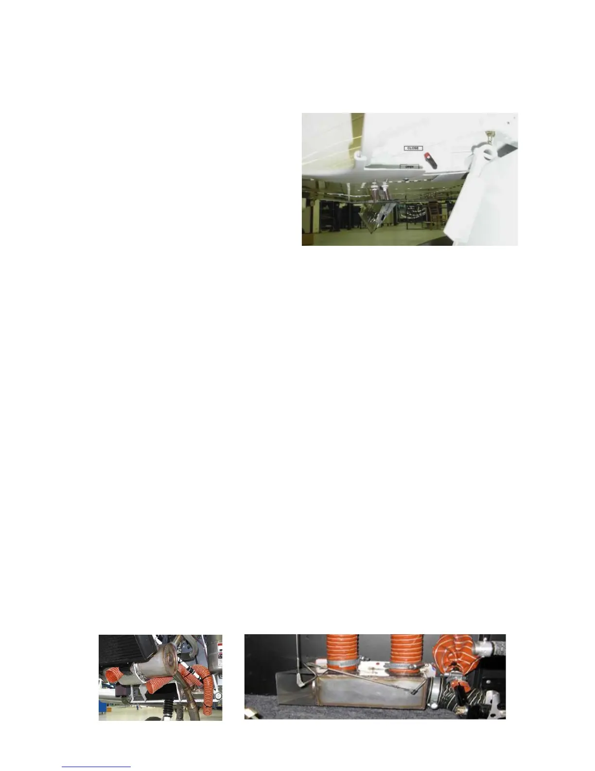
The fuel system incorporates a sump and drain
valve to collect water and other contaminants in
the fuel. The drain outlet is located under the
fuselage, near the starboard flap root, and is
accessible when the flaps are fully extended.
(See photo on the right). The tank’s vent also
terminates adjacent to this drain outlet.
A filler cap is installed on the starboard side of
the fuselage.
Fuel quantity is indicated on the panel by a gauge operating from a float sender inside the tank.
The aircraft must be on level ground. It is highly recommended to have accurate knowledge of fuel
load before each flight. Timing fuel burn is also recommended during each flight.
2.22 Cooling System
Two forms of cooling keep engine temperatures under control: cylinder heads are liquid cooled;
cylinders are ram air cooled. A coolant radiator is mounted in the front of the lower engine cowling;
coolant is forced through the radiator to the cylinder heads by a water pump driven from the
crankshaft. Coolant then passes from the top of the cylinder heads to an expansion tank mounted
on top of the engine. This tank allows the coolant to expand and is fitted with a pressure relief cap
and return valve system. Excess coolant passes through the cap into a small plastic overflow
bottle mounted on the firewall.
The coolant level in the expansion tank should be checked before the first flight of the day and
should reach the bottom of the filler neck. Normal coolant level in the overflow bottle is level is ½
to 2/3 up the tank (0.2 litres); minimum level is 25mm from the bottom.
2.23 Cockpit Heating System
One intake air hose routes outside air to the heat exchanger (a jacket around the exhaust), where
the air is heated. It is then led through a valve on the firewall to the mixing chamber on the cockpit
floor. When the valve is closed, the air is exhausted via an outlet air hose exiting under the
fuselage. A second hose feeds outside air directly through the valve on the firewall to the mixing
chamber on the cockpit floor. It is recommended to fit a carbon monoxide detector
Hot air and cold air valves are operated by a Bowden cable running to small control knobs on the
panel.
Demisting/defrosting of the windshield is performed by hot air being fed from the mixing chamber
on the firewall to the internal space of the canopy frame molding and then through a row of holes
along the bottom edge of the tinted plastic canopy.