EV-97 Eurostar SL Microlight Maintenance Manual GEN/EUR/04 Issue 4 36
9.2 Rudder Pedal Adjustment
At the base of each rudder pedal an adjustment mechanism permits the pedal to be moved
backwards or forward to accommodate different leg lengths. Pull the top of the plunger’s lever to
the left on the pilot side, or to the right on the co-pilot side, to withdraw the plunger from one of the
three holes in the plate. Move the rudder pedal to the desired position, then release the plunger
lever. Gently move the rudder pedal so that it locates in the nearest hole. Check that the pedals
are aligned when the rudder and nose wheel point straight ahead.
10. Trim Tab Control Cable Tension
Check the tension of the trim tab control cables according to the following procedure:
With the trim tab control lever set to the neutral position, block the elevator to prevent
movement. Apply a load of 20 N (2kg) to the trim tab trailing edge using a weight or spring
balance. The trim tab deflection must not exceed 5 mm from its original position. If the trim tab
deflection exceeds this value, then it is necessary to adjust the trim tab cable preload using its
adjusting screws.
11. Jacking the Aircraft
Because the empty weight of this airplane is low it is easy to lift the airplane using 2 people.
First prepare two suitable trestles to support the aircraft.
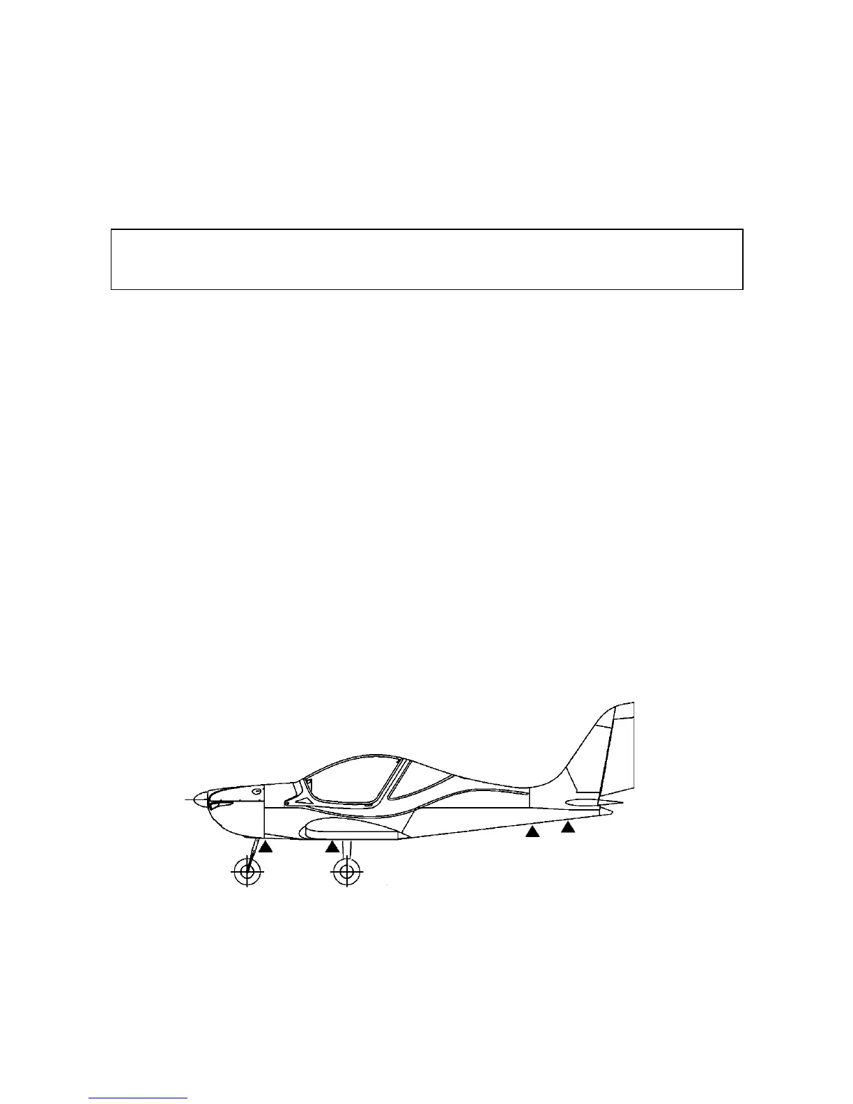
The aircraft should be lifted by the following parts, as shown below:
• Press-down on the rear of the fuselage in front of the fin to lift the front and then support it
under the firewall. The fuselage nose may be supported under the horizontal tube of the
engine mount or under the nose landing gear attachment to the fuselage.
• To lift the wings, raise them using the wings lower surface at the main spar. Do not lift by the
composite wing tips. Do not apply localised pressure to the skins.
12. Puncture Repair
Support the aircraft to lift the wheel with the punctured tyre.