EHN3261/3361
5
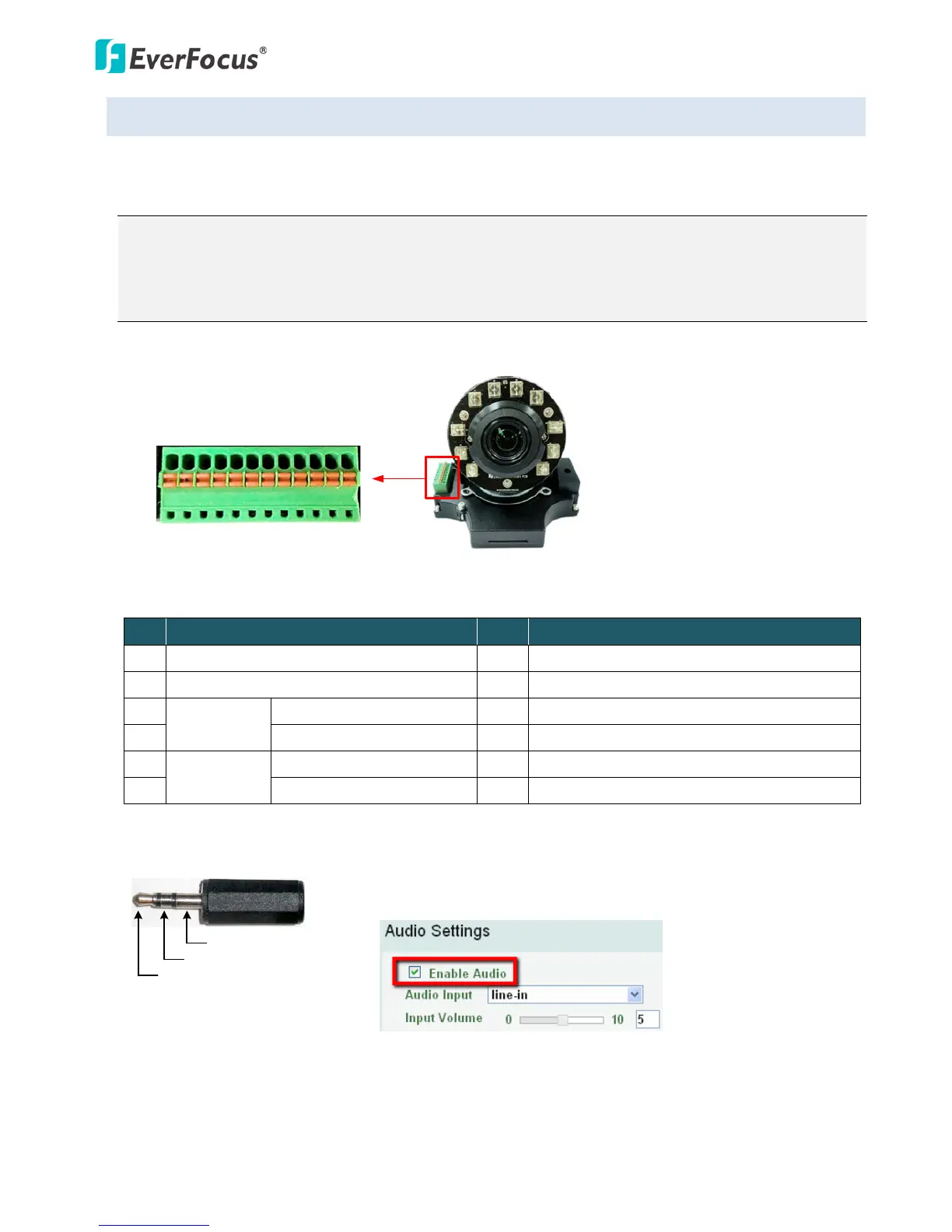
4.3 Terminal Block
The I/O terminal block, located on the camera module, can be used to develop applications for alarm
input and output, two-way audio, TV-output or a variety of other functions.
Note:
1. You can unplug the terminal block from the camera module for easier wiring.
2. Be sure to prepare microphones with TRS connector (see TRS Connector image below). Also,
microphones with a (built-in) amplifier and external power supply are required.
Camera Module
1 2 3 4 5 6 7 8 9 10 11 12
Pin Assignment
No. Functions No. Functions
1 12 VDC Input 7 Audio Input C (TRS Line-in)
2 Digital GND 8 Audio GND
3
Alarm Out
Alarm Output C (+) 9 Audio Output
4 Alarm COM C (-) 10 Audio GND
5
Alarm In
Alarm Input C (+) 11 CVBS Output
6 Digital GND (-) 12 Digital GND
TRS Connector
Left Channel (Tip)
Right Channel (Ring)
Ground (Sleeve)
To activate the Audio function, the Enable Audio must be checked.
See Audio Settings in 7.2.1 Streaming and Audio.