TRANSOM HEIGHT . .
The proper transom (verttcal) height tor the Standard Length Model
ts
14-1/2
to lS-1/2" The proper transom (vertical) hetght
for
the
L~ng
Shaft
~ode!
is
19-
1/2 to 20-1/2". If the transom is too high. the propeller wtll operate
1~
turbulent
water with lowered effictency. Overheatmg may result.
If
the transom
ts
too
low,
excess
1
ve
drag may result and your boat will not perform
properly
.
D
NOTE:
We
recommend usmg an accessory transom plate to
protect
your
boat
and help prevent loss of motor
See
your
Dealer.
PROPELLER SELECTION
Your motor is equtpped with a propeller that will perform satisfactorily under
average condttions. However, since some boats have a varying speed potential, it may
be
necessary to install a propeller having
an
increased
or
decreased blade pitch to
achieve maxtmum performance.
When
operating your motor
at
full throttle under normal load
conditions
the engine
RPM
is
the controlling factor 10 determining the correct propeller blade pitch for your
rig.
To
obtam peak performance. the engme
RPM
under these operating conditions
should
be
tn
the upper half of the FULL SPEED
RPM
OPERATING RANGE. (See
SPECIFICATIONS.) If
the engine
RPM
is
on
the low side
of
the recommended range,
install a propeller of reduced pitch and the engine
RPM
will increase.
If
the engine
RPM
ts
above recommended
RPM,
install a propeller
of
an
increased pitch to reduce
engine
RPM.
See
your DEALER.
It
1s
suggested that a tachometer
be
uttlized to accurately check engine
RPM
.
See
your DEALER.
He
will
be
pleased to assist you
in
obtaining maxtmum performance
from your boat and motor.
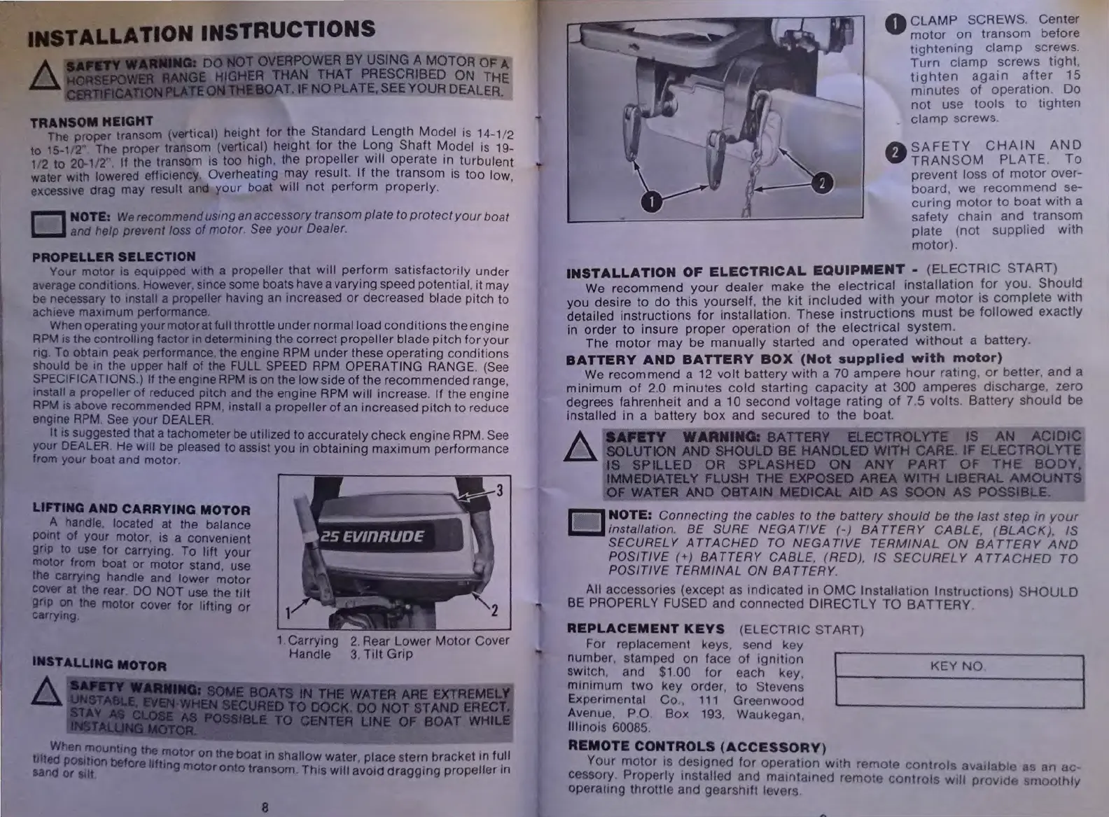
LiniNG
AND CARRYING MOTOR
A handle. located at the balance
pomt of your motor, is a conventent
grip
to
use
for carrymg. To lift your
motor from boat or motor stand, use
the
carrymg handle and lower motor
co11er
at
the rear.
DO
NOT use the tilt
gnp
on
the
motor cover for lifting or
carrymg
INSTALLING MOTOR
A
1 Carrying
2.
Rear Lower
Motor
Cover
Handle
3.
Tilt
Grip
When
mountmg the mot
th
. .
ttlted
POSltton
bet
If
. or on e boat
tn
shallow water, place stern bracket
tn
f~ll
sand or
Stlt,
ore
1
ttng motor onto transom. Thts will avoid dragging propeller
tn
8
..
0
CLAMP
SCREWS.
Center
motor
on transom before
ttghtening
clamp
screws.
Turn
clamp
screws
ttght
,
tighten
again
after
15
mmutes
of
operation.
Do
not
use
tools
to
tighten
clamp
screws
A
SAFETY
CHAIN
AND
V
TRANSOM
PLATE
.
To
prevent loss
of
motor
over-
board, we
recommend
se-
curing
motor
to
boat
with
a
safety
chain
and
transom
plate
(not
supplied
with
motor).
INSTALLATION
OF
ELECTRICAL
EQUIPMENT
-
(ELECTRIC
START)
We recommend
your
dealer
make
the
electrical
installation
_
for
you.
Should
you desire
to
do
this
yourself,
the
kit
inclu?ed
with
your
motor
IS
complete
With
detailed
instructions
for
installation. These rnstruct1ons
must
be
followed
exactly
in
order
to
insure
proper
operation
of
the
electrical
system
.
The
motor
may be
manually
started
and
operated
without
a
battery
BATTERY
AND
BATTERY
BOX
(Not
supplied
with
motor)
We recommend a 12
volt
battery
with
a
70
ampere
hour
ratmg,
or
better,
and
a
minimum
of
2.0
minutes
cold
starting
capacity
at
300
amperes
discharge,
zero
degrees
fahrenheit
and a 10 second
voltage
rating
of
7.5 volts.
Battery
should
be
installed in a
battery
box
and secured
to
the
boat.
A
aAPaTY
WARNING: BATTERY ELECTROLYTE IS
AN
ACIDIC
~
SOLUTION AND SHOULD BE HANDLED WITH CARE. IF ELECTROLYTE
IS SPILLED OR SPLASHED
ON
ANY
PART
OF
THE
BODY,
IMMEDlATELY FLUSH THE EXPOSED AREA WITH LIBERAL AMOUNTS
OF
WATER
AND OBTAIN MEDICAL AID
AS
SOON
AS
POSSIBL
__
E
.~-
·
·
-~~-----'
~NOTE:
Connecting
the cables to the
battery
should
be
the
last
step
in
your
&l...J
msta/latJon. BE SURE
NEGATIVE
(-)
BATTERY
CABLE,
(BLACK).
IS
SECURELY
ATTACHED
TO
NEGATIVE
TERMINAL
ON
BATTERY
AND
POSITIVE
(+)
BATTERY
CABLE, (REO), IS
SECURELY
A
TTACHEO
TO
POSITIVE
TERMINAL
ON
BATTERY
.
All accessories (except as rndicated in
OMC
InstallatiOn
Instructions)
SHOULD
BE PROPERLY FUSED and
connected
DIRECTLY
TO
BATTERY
REPLACEMENT
KEYS
(ELECTRIC
STAAT)
For replacement keys, send key
number. stamped on face
of
ignition
sw1tch, and $1.00 for each key,
mmtmum
two
key order,
to
Stevens
Experimental
Co
, 111
Greenwood
Avenue, P 0 . Box 193, Waukegan,
Illinois 60085
REMOTECONTROLS(ACCESSORY)
KEY
NO
.
Your
motor
is destgned
for
operat1on
with
remote
controls
availabl•~
as an
ac
·
cessory. Properly mstalled and
mamtamed
remoto
controls
will
provtd
smoothly
operating
throttle
and
gearshift
levers
 Loading...

