302
TRIM AND TILT
ELECTRICAL CIRCUIT TESTS
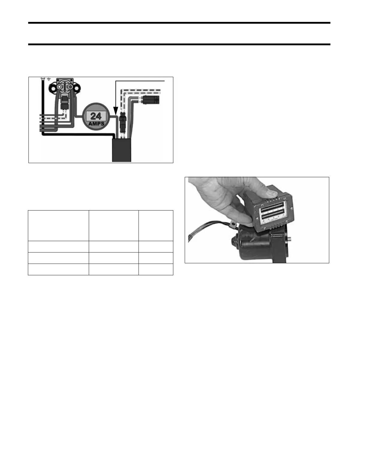
Connect a 0 to 100 A DC ammeter in series
between the battery side of the starter solenoid
and the red lead to the trim/tilt relay module.
Observe ammeter and a stopwatch while running
hydraulic unit through several complete cycles.
Compare test results to the values listed:
Test results include three basic possibilities:
A. Low current draw – Check for:
• Valves leaking
• Pump damaged
• O-rings leaking
B. High current draw – Check for:
• Pump binding
• Motor binding
• Valves sticking
• Relief valve springs damaged
C. Normal current draw, slow operating
speed – Check for:
• Damaged pump control piston
• Malfunctioning check valves
Trim and Tilt Motor No Load Test
IMPORTANT: Securely fasten motor in a suit-
able fixture before proceeding with this test.
Use a battery rated at 360 CCA (50 Ah) or higher
that is in good condition and fully charged to per-
form this test.
Connect a 0 to 25 A ammeter in series with the
battery positive (+) terminal, ammeter red lead
toward terminal.
Attach or hold a vibration or mechanical tachome-
ter to the motor while performing this test.
Monitor motor RPM and current draw.
The motor shaft must rotate clockwise, as viewed
from the pump end, when positive (+) is applied to
the blue lead, and negative (–) is connected to
green lead.
1. Red lead 005441
Mode
Normal
Current Draw
Time in
Seconds
Stall UP 11 to 16 Amps –
Stall DOWN 16 to 22 Amps –
Full Range UP – 13 to 19
Full Range DOWN – 10 to 16
1
30957