304
TRIM AND TILT
SERVICING
SERVICING
Removal
Raise the outboard and engage the tilt support.
Remove the blue and green wires from pump
motor connector housing.
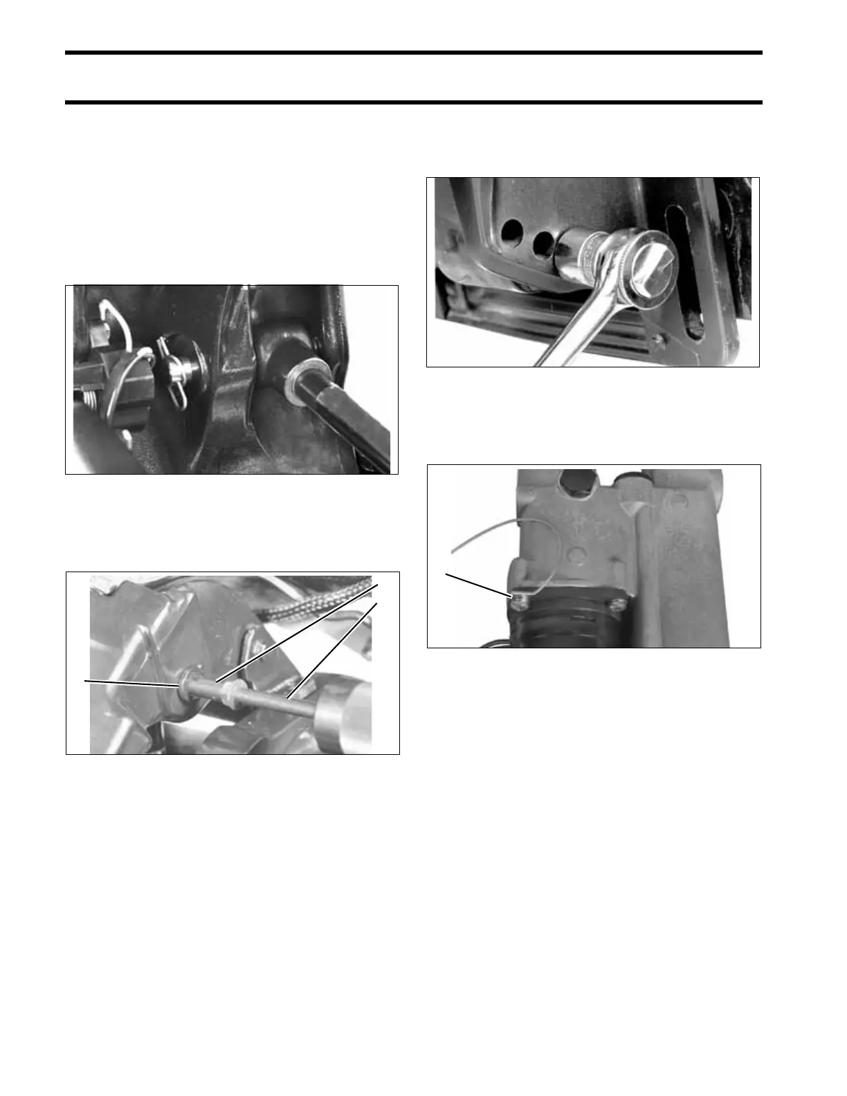
Remove the spring clip from the cylinder pin.
Thread Adapter, P/N 340624, onto Slide Hammer,
P/N 391008. Screw the adapter into the cylinder
pin and remove the pin.
Remove one of the 3/4 in. locknuts from the angle
adjustment rod. Remove the rod from the stern
brackets.
Remove the unit from the stern brackets far
enough to remove the ground lead from the pump
motor mounting screw.
Disassembly
Thoroughly clean the unit before disassembling.
Scrub all outside surfaces with a stiff brush and
hot, soapy water to prevent surface dirt from con-
taminating internal parts.
Always use a lint free shop cloth when handling
power trim/tilt components.
If painting the unit is required, paint it after it is
completely assembled. Painting of individual com-
ponents may cause flakes of paint to enter the
15493
1. Thread adapter
2. Slide hammer
3. Cylinder pin
39434
1
2
3
18941
1. Ground lead 002527
1