WIRING
POWER CONNECTION
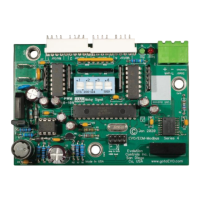
Power the EVO/ECM-Modbus RTU with a ~24V 50/60 Hz 10 VA low voltage
power source. Connect the hot side of the power source to the ~24V
connection. Connect the neutral side of the power source to the neutral
connection. Observe all building and electrical code requirements
concerning low voltage power sources and wiring to insure a safe, reliable
installation. In most jurisdictions the neutral must be earthed.
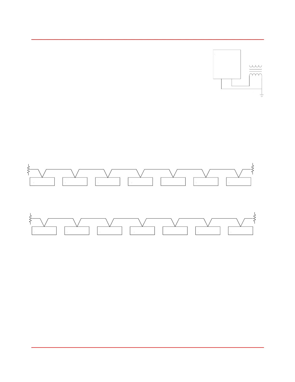
TRUNK CONNECTION
A single trunk routes from one EVO/ECM-Modbus RTU to the next, connecting up to 31 RTUs to
the Modbus RTU master. The trunk may be up to 4000 feet long. Connect a 120-ohm 1/4-Watt
terminating resister at each end of the trunk. The most common connection places the Modbus
RTU master at one end of the trunk. Many Modbus RTU masters have a non-removeable built in
terminator or use an impedance altering means to provide line bias. These masters must be
placed at the end of the line.
When possible, placing the Modbus RTU master in the center of the trunk improves application
versatility, often reduces installation costs, and improves communications reliability.
The trunk cable field terminates to a plug-in connector at each RTU. Use a twisted pair cable with
an overall foil shield. Recommend the use of EIA RS-485 cable 22-24 AWG twisted and balanced,
with an impedance of 100-130 ohms, a capacitance below 100 pF per meter (30 pF per foot), with
a braided shield. Connect the shield to the Shield/Common terminal at each RTU as shown in the
picture below. Do not ground the shield at the RTUs. The shield must be chassis grounded at the
master only.
The shield wire is usually not insulated. Keep the shield leads short between the cable sheath and
the shield connection. Let the other wires be longer!