www.evolutionfury.com
17
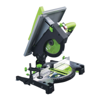
WORKPIECE SUPPORTS (Fig. 8)
Workpiece supports can be fitted to both
sides of the machine base if required.
• LoosentherelevantWorkpieceRetaining
Screw located in a socket at the top front
of the machine base.
• InserttheWorkpieceSupportintothe
holes machined in the base.
NOTE: The Workpiece Support should be
pushed ‘fully home’ into the machine base.
Correct installation will require approximately
65mm of the Workpiece Support to slide into
the machine base.
• FastentheWorkpieceSupportintothe
base by tightening the Retaining Screw.
Workpiece Supports can be very useful in
providing extra support for long workpieces
when using the Fury6 in Mitre Saw
configuration.
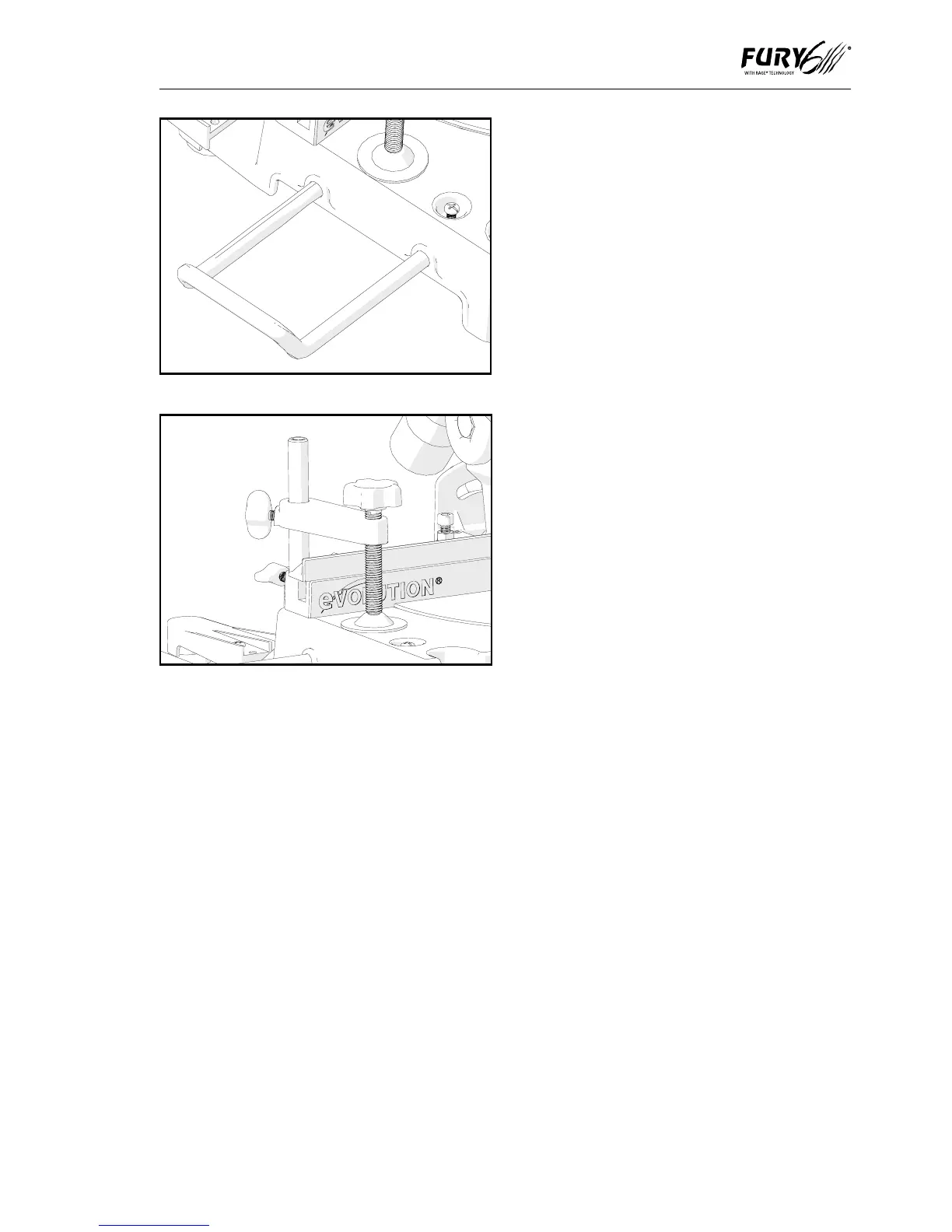
HOLD DOWN CLAMP (Fig. 9)
A Hold Down clamp is supplied with the Fury6.
Two sockets (one on either side) are
incorporated into the rear of the machines
fence.
• Fitthepillaroftheclampintothesocket
that best suits the cutting application,
ensuring that it is pushed fully down.
• Tightenthefencethumbscrewtolockthe
pillar of the Hold Down Clamp into the
fence socket.
• Puttheworkpieceontotherotarytable
and against the fence.
•AdjusttheHoldDownClampsothat
it securely holds the workpiece to the
rotary table.
• Beforeattemptinganycuttingcheckto
ensure that the clamp does not interfere
with the blade path as the Cutting Head
is lowered.
OPERATING INSTRUCTIONS
MITRE SAW CONFIGURATION
WARNING: It is important that the operator
is adequately trained in the use, adjustment
and operation of the machine, and has read
the Instruction Manual before commencing
operations.
NOTE: We recommend that when the
Fury6 is being used as a Mitre Saw, the
complete Fence Assembly is removed from
the machine as stored safely for future use.
1. Releasing the Cutting Head
NOTE: When configured in Mitre Saw
mode the Cutting Head will be automatically
locked in its upper position with the
Retractable Lower Blade Guard completely
covering the blade teeth.
Fig. 9
Fig. 8