www.evolutionfury.com
27
NOTE: To check and adjust the Bevel
Angles the machine must be in Mitre Saw
configuration.
0
0
BEVEL ANGLE
At 0
0
Bevel Angle the blade should be
perpendicular and at exactly 90
0
to the
Rotary Table. An accurate engineers square
(not supplied) is needed to check the 0
0
Bevel Angle.
To check:
• EnsurethattheCuttingHeadisinthe
vertical position, against its stop with the
Bevel Pointer indicating 0
0
Bevel Angle.
• TightentheBevelLockHandle.
• LowertheCuttingHeadtoitslowest
position. The Retractable Lower Blade
Guard will rotate up into the machine.
• Theengineerssquarecannowbeusedto
check the angle between the blade and
the Rotary Table.
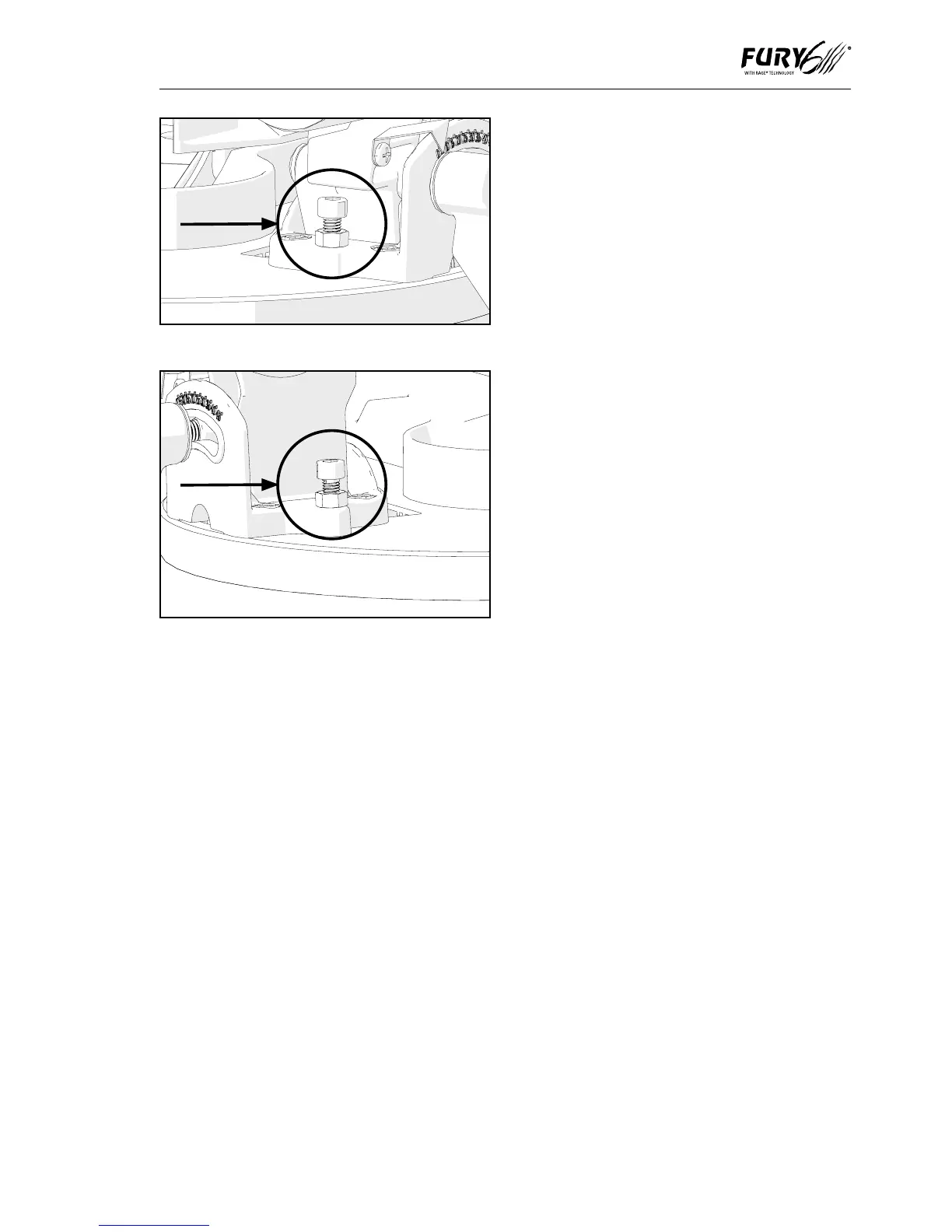
If adjustment is required:
NOTE: The Cutting Head will need to be
tilted to gain access to the 0
0
Bevel Stop
Adjustment Screw.
• Loosenslightlythe0
0
Bevel Stop
Adjustment Screw locknut. (Fig. 31)
• UseanAllenKeytoturntheBevelStop
Screw clockwise or counterclockwise
as required.
• Whenexactalignmentbetweenthe
blade and Rotary Table is achieved,
tighten the locknut.
45
0
BEVEL ANGLE
The 45
0
Bevel Angle can be checked in a
similar manner to the 0
0
Bevel Angle. An
accurate 45
0
Engineers Set Square (not
supplied) will be required.
To check:
• EnsurethattheCuttingHeadistiltedto
the 45
0
position, against its stop, with the
Bevel Pointer indicating 45
0
Bevel Angle.
• TightentheBevelLockHandle.
• LowertheCuttingHeadtoitslowest
position. The Retractable Lower Blade
Guard will rotate up into the machine.
• UsetheEngineers45
0
Set Square to
check the angle of between the blade
and the Rotary Table.
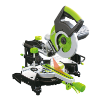
If adjustment is required:
NOTE: The Cutting Head will need to be
tilted to gain access to the 45
0
Bevel Stop
Adjustment Screw.
• Loosenslightlythe45
0
Bevel Stop
Adjustment Screw locknut. (Fig. 32)
• UseaHexKeytoturntheBevelStop
Screw clockwise or counterclockwise
as required.
• Whenexactalignmentbetweenthe
blade and Rotary Table is achieved,
tighten the locknut.
Fig. 31
Fig. 32