16. NEVER STAND ON TOOL. Serious injury could occur if the tool is
tipped or if the cutting tool is unintentionally contacted.
17. CHECK DAMAGED PARTS. Before further use of the tool, a guard or
other part that is damaged should be carefully checked to determine
that it will operate properly and perform its intended function – check
for alignment of moving parts, binding of moving parts, breakage of
parts, mounting, and any other conditions that may affect its operation.
A guard or other part that is damaged should be properly repaired or
replaced.
18. Wear eye protection.
19. Keep hands out of path of saw blade.
20. Do not operate saw without guards in place.
21. Never reach around saw blade.
22. Turn off tool and wait for saw blade to stop before moving workpiece
or changing settings.
23. Disconnect power before changing blade, servicing or cleaning.
24. To reduce the risk of injury, return carriage to the full rear position after
each crosscut operation.
SAVE THESE INSTRUCTIONS
FOR FUTURE REFERENCE
ADDITIONAL SAFETY INSTRUCTION
1. Although compact, this saw is heavy. To reduce the risk of back injury,
get help whenever you have to lift the saw.
2. To reduce the risk of back injury, hold the tool close to your body when
lifting. Bending your knees so you can lift with your legs, not your
back. Lift by using the handhold areas at each side of the bottom of
the base.
3. Never carry the mitre saw by the power cord or the trigger grip of the
handle. Carrying the tool by the power cord could cause damage to
the insulation or the wire connections resulting in electric shock or
re.
4. Before removing the saw from the carton tighten the slide lock knob
to guard against sudden movement.
5. Place the saw on a secure stationary work surface and check the saw
over carefully.
6. Warning. Do not stare directly at the laser beam. A hazard may exist
if you deliberately stare into the beam, please observe all safety rules
as follows.
- The laser shall be used and maintained in accordance with the
manufacturer instructions.
- The laser beam shall not be deliberately aimed at personnel
and shall be prevented from being directed towards the eyes of a
person.
- Always ensure the laser beam is aimed at the workpiece
without reective surfaces, i.e. wood or rough coated surfaces are
acceptable.
- Do not change the laser light assembly with a different type.
SPECIFICATIONS
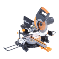
Model Rage 3
Motor (230v-240v ~ or 110v ~ 50/60 Hz) (Watts): 2000
RPM No Load (min-1): 2500
Recommended Maximum Duty Cycle (Minutes): 30
Sound Pressure Level (Under Load) (dB(A)): 98
Vibration Level (Under Load) (m/s
2
): 1.98
Weight: 19.6Kg
Blade Dimensions
Maximum Diameter: (10”) 255mm
Bore Diameter: (1”) 25.4mm
Thickness: (1/16”) 2mm
Maximum Cutting Capacity
Mitre Bevel Max Width of Cut Max Depth of Cut
90º 90° 300mm (11.81””) 75mm (2.95”)
45°L / 45°R 45° 210mm (8.26””) 40mm (1.57”)
45°L / 45°R 90° 210mm (8.26””) 75mm (2.95”)
90° 45° 300mm (11.81””) 40mm (1.57”)
5. Turn on saw and allow the saw to reach full speed.
6. Press the lower guard unlock lever for saw head release.
7. Push the saw handle down and cut the workpiece.
8. After cut is complete turn off saw, allow blade to completely stop.
WARNING: For your convenient use, the saw has a blade brake. Never
rely on it to replace proper use of the guard on your saw.
BODY AND HAND POSITION
1. Never place hands near cutting area and keep hand away from the
path of blade.
2. Hold workpiece rmly to the fence to prevent movement toward the
blade.
3. Before making a cut. Make a dry run with the power off so you can
see the path of the blade.
5. Keep hands in position until trigger has been released and the blade
has completely stopped.
MITRE CUT
An angle of up to 45° left or right can be obtained using the unit.
1. Loosen the mitre angle lock.
2. Pull up the mitre angle set lever.
3. Turn the table unit to the desired angle is indicated on the mitre angle
pointer.
4. Tighten the angle lock knob to hold the desired angle.
5. Start the saw and allow it to reach full speed before commencing the
cut.
BEVEL CUT
1. Loosen the bevel angle lock.
2. Move the blade to desired bevel angle.
3. Stand to the left side of the handle to make the cut.
COMPOUND CUT
When a compound cut is required. Select the desired bevel and mitre
positions.
CUTTING BOWED MATERIAL (Fig 10 & 11)
Before cutting a workpiece, check to make sure it is not
bowed. If it is bowed, the workpiece must be positioned
and cut as illustrated. Do not position workpiece
incorrectly or try to cut the workpiece without the
support of the fence. This will cause pinching of the
workpiece on the blade. The workpiece could suddenly
jump or move and your hand could hit the blade.
CUTTING COMPOUND MITRES
To aid in making the correct settings, the compound
angle setting chart below has been provided. Since
compound cuts are the most difcult to accurately
obtain, trial cuts should be made in scrap material, and
much thought and planning made, prior to making your
required cut.
WARNING: Always unplug the tool before making any
assembly, adjustments or changing accessories.
COMPOUND ANGLE SETTINGS FOR POPULAR STRUCTURES
Each B (Bevel) and M (Mitre) Setting is given to the closest 0.005°
PITCH
OF
SIDE
N U M B E R O F S I D E S
4 5 6 7 8 9 10
0°
M- 45.00°
B- 0.00°
M- 36.00°
B- 0.00°
M- 30.00°
B- 0.00°
M- 25.71°
B- 0.00°
M- 22.50°
B- 0.00°
M- 20.00°
B- 0.00°
M- 18.00°
B- 0.00°
5°
M- 44.89°
B- 3.53°
M- 35.90°
B- 2.94°
M- 29.91°
B- 2.50°
M- 25.63°
B- 2.17°
M- 22.42°
B- 1.91°
M- 19.93°
B- 1.71°
M- 17.94°
B- 1.54°
10°
M- 44.56°
B- 7.05°
M- 35.58°
B- 5.86°
M- 29.62°
B- 4.98°
M- 25.37°
B- 4.32°
M- 22.19°
B- 3.81°
M- 19.72°
B- 3.40°
M- 17.74°
B- 3.08°
15°
M- 44.01°
B- 10.55°
M- 35.06°
B- 8.75°
M- 29.15°
B- 7.44°
M- 24.95°
B- 6.95°
M- 21.81°
B- 5.68°
M- 19.37°
B- 5.08°
M- 17.42°
B- 4.59°
4 7
 Loading...