charger 3 Quick Installation Guide
Tools
• A set of Torx, Phillips, and flathead
screwdrivers with insulated handles
• Torque limited drill or cordless
screwdriver, drill bit for masonry (8 mm)
• Hammer drill and bits
• Electrician kit, including pliers, strippers,
ferrule and RJ-45/22 crimping tools
Materials
• Conductors (insulated single-core or
stranded), conduit
e-downs
• Signal cables (UTP5 cable)
• Connectors (RJ-45/22) and ferrules
• Insula
aterials
• Wall anchors and screws (included)
• Hole template for wall anchors (see back)
1. Locate and drill anchor holes
• Select a suitable loca for the sta
as described in the User Manual
• Prepare an 8 mm masonry drill and the hole
template by flipping this sheet over
• Ensure that the hole template
is level on its centreline
• Drill the holes to a depth >50 mm and clear
the debris
• Tap the anchors into place with a mallet
un
re flush with the wall
2. Install the moun ate
• Locate and prepare 4 4.8x50mm screws
• Unscrew the moun
ate from the
charger via the service opening and orient
it as shown
• Insert and drive the screws through the
moun
ate and into the anchors
un
at htly pressed to the wall
3.
Mount the charger
•
Slide the charger body onto the
moun
ate fins and lever it down
• Locate the moun
rew from step 2
and place it back into the charger service
opening. Tighten to firmly secure the
device to the plate
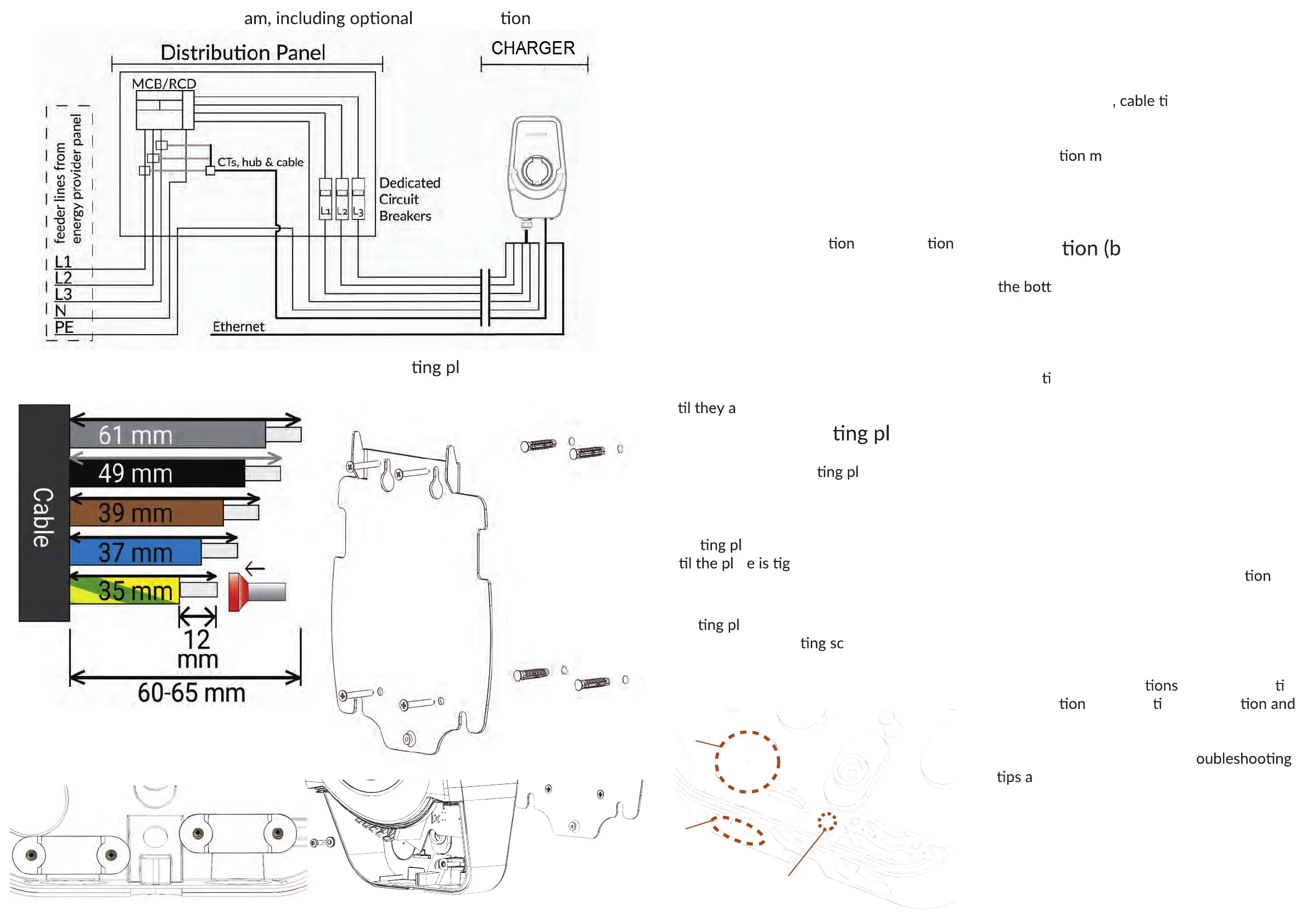
4. Complete the electrical
installa
reaker OFF!)
•
The charger supply can be routed from
om (via a cable gland) or from the
back via a punch-out hole, for which a rubber
grommet is provided. See the diagram below.
• Route and secure the power/signal cables
to the device and feed them through their
respec
ve glands. Fasten the cable clamp(s).
• Strip the power cable and the individual
conductors to the correct lengths
• Crimp the power cable ferrules (stranded
wires) and the signal cable RJ-45 if used
• Insert the power conductors and signal
cable into the charger motherboard
• Locate and install the SIM card if used
5. Power and configure the
charger 3
• Check and verify that the installa
follows the wiring diagram (see next page)
• Re-set the circuit breakers feeding the
charger to power the device
•
Connect to the charger using the
installer app or web client
• Follow the instruc
for the respec ve
configura
tool to ac vate the sta
customize its smart features
•
Test the charger with an EV or
dedicated EVSE tester tool. Tr
re listed in the User Manual.
6.
Enjoy your Smart
charger!
Moun ate installation and
securing the charger 3
Power cable stripping lengths.
Stranded conductors require ferrules
Overall electrical wiring diagr
CT connec
input cable clamp
tethered cable clamp
Cable clamp locaons. The input
cable clamp is not fixed to the body.
backside
cable
entry
bottom cable
gland position
UTP signal
cable grommet