page 22 of 49
3.1. charger wiring scheme
The power and signal conductors can be connected to the device after the charger body has
been mounted to the wall and the cable glands have been installed. The conductors are pulled
through the gland with enough slack to make the connections without strain. The charger uses
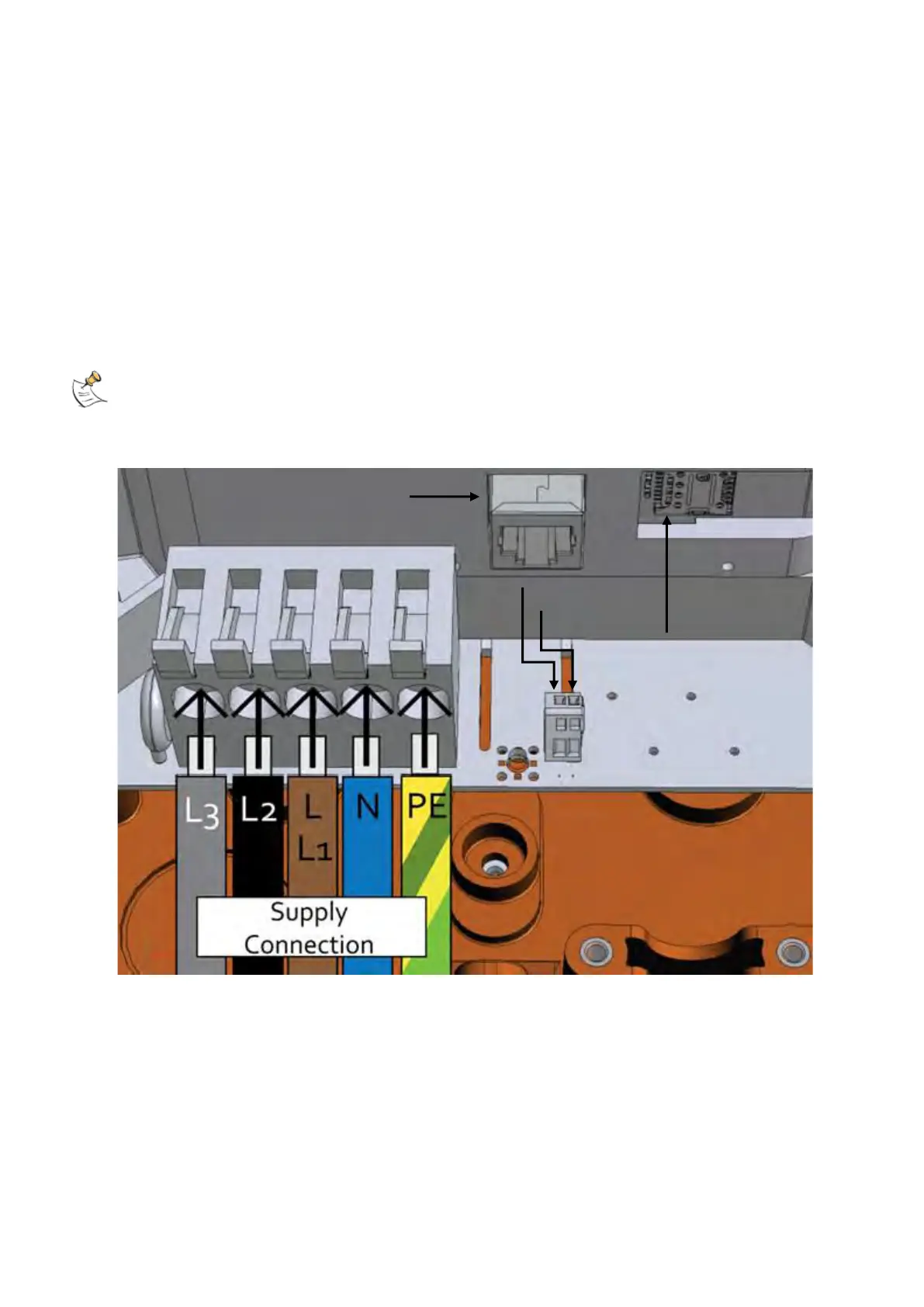
lever terminal blocks for all connections except for the output PE terminal for tethered models,
which requires a round cable terminal lug.
charger series 3SLC/3TLC can be configured as either single or three-phase models. Observe
the respective wiring procedure and subsequent commissioning steps to ensure proper
operation.
Safety note: before working with bare conductors, ensure that the power is disconnected and
the circuit is not live!
3.1.1. Socketed
Socketed charger models need the following setup:
• Communication cable (Ethernet and/or RS-485 connection) – to RJ-45 Port
• SIM Card for network connection
• Power:
o Single-phase models – L/N/PE connection from distribution board
o Three-phase models – R/S/T (L1/L2/L3) + N + PE connection from distribution
board