page 21 of 49
In installations without RS-485 peripherals (CT clamps or energy meter) and with Ethernet
connectivity, a standard Ethernet patch cable can be used to connect the charger and a router.
For installations with 485 communication, the wiring connects to the charger via the same RJ-
45 port on the device by means of 4 unoccupied connections (2 twisted pairs) on the connector.
Since every installation will have custom lengths of cable runs, the installers will determine the
appropriate lengths of signal cables to use (up to 30 m for both Ethernet and CT clamp/energy
meter connections).
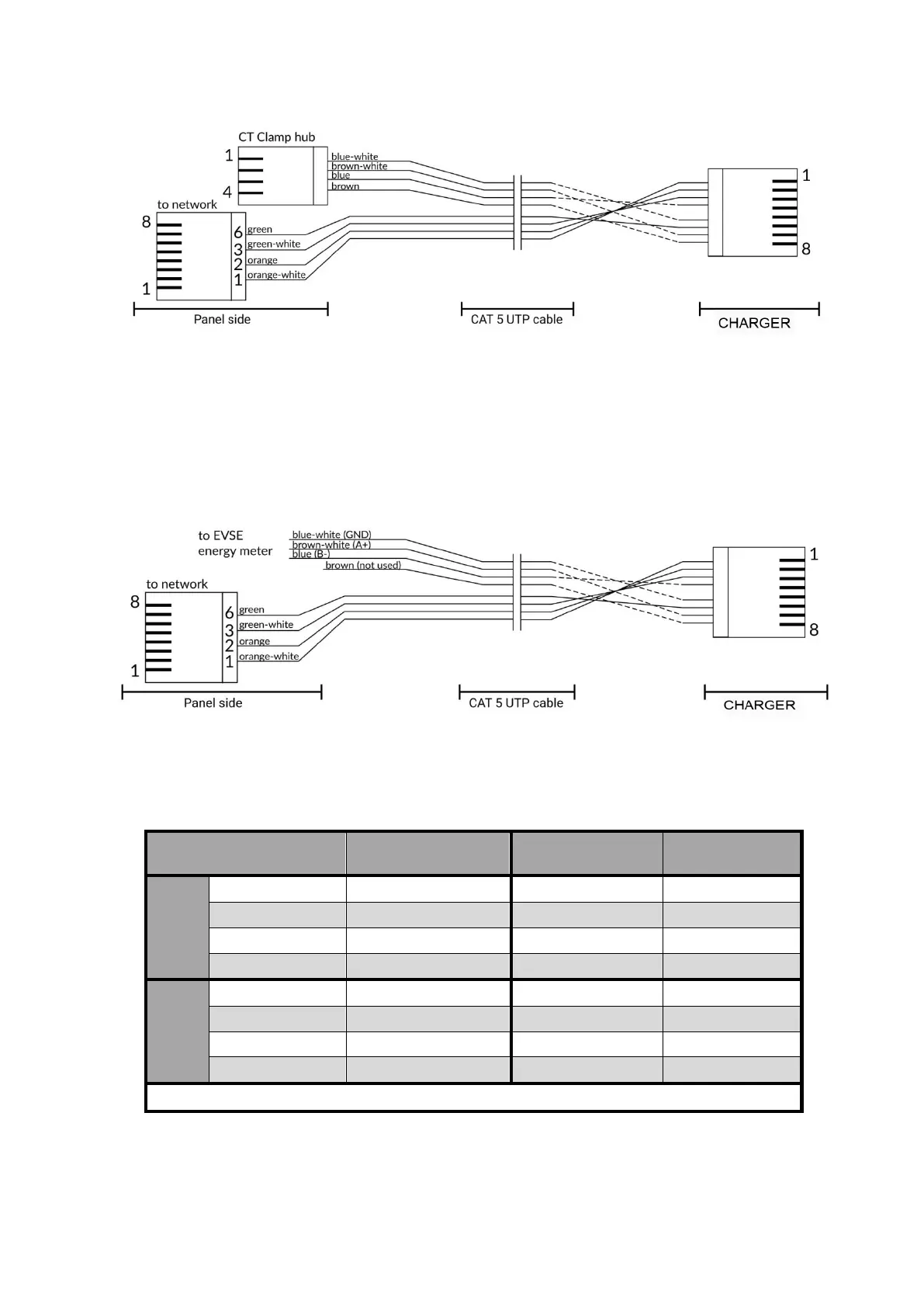
Due to the universal availability of CAT5 UTP cable, it can be used as a combined cable for the
Ethernet and CT clamp connections, avoiding a second run of signal wires. Two twisted pairs are
used for the CT clamp connection and two for the Ethernet Tx and Rx lines. The following table
summarizes a suggested connection scheme, consistent with RJ-45B wiring scheme.
charger RJ-45
Pin #
* Pins 4,5,7,8 must not be connected!
Combined Ethernet and RS-485 cable pinout for energy meter connection
Combined Ethernet and RS-485 cable pinout for CT clamp connection