Operation
AdjustingtheSideBumpers
(RearDischargeUnitsOnly)
Mountthesidebumpersinthetopholeswhen
operatinginheightofcutshigherthan21/2inches
(64mm)andinthecenterholeswhenoperatingin
heightofcutslowerthan21/2inches(64mm).
Note:Whenbumpersbecomeworn,switchthe
bumperstotheoppositesidesofthemower,ipping
themover.Thisallowsthebumperstobeusedlonger
beforereplacingthem.
1.Stopthemachineandmovethemotioncontrol
leversoutwardtotheneutrallockedposition.
2.DisengagethePTO.
3.Engagetheparkbrake.
4.Stoptheengine,removethekeyandwaitforall
movingpartstostop.
5.Positionthetransportlockinthelatching
position.
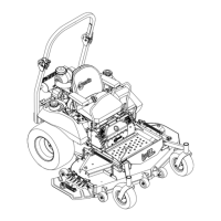
6.Removetheboltsandnutsfromeachbumper.
Figure21
1.Bolt3.Nut
2.Bumper
7.Moveeachbumpertothedesiredpositionand
securethemwiththeboltsandnuts.Torquenut
to10-12ft-lb(14-16N-m).
Note:Onlyusethetoporcentersetsofholesto
adjustthebumpers.Thebottomholesareused
whenswitchingsides,atwhichtimetheybecome
thetopholesontheothersideofthemower.
AdjustingtheSuspensionSeatFor
“B1”,“B2”,and“B3”ModelsOnly
Thesuspensionsystemadjuststoprovideasmooth
andcomfortableride.Adjustingthereartwoshock
assembliesistheeasiestandquickestadjustment
forchangingthesuspensionsystem.Positionthe
suspensionsystemwhereyouaremostcomfortable.
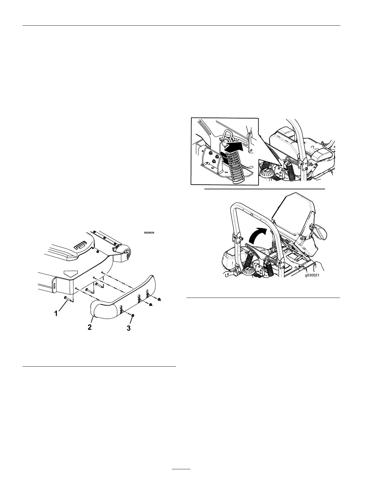
•UnlatchingtheSeat
Figure22
•AdjustingtheRear,ShockAssemblies
Theslotsfortherear,shockassemblieshave
detentpositionsforreference.Therear,shock
assembliescanbepositionedanywhereintheslot,
notjustthedetentpositions.
Thefollowinggraphicshowsthepositionfora
softorrmrideandthedifferentdetentpositions
(Figure23).
36
 Loading...