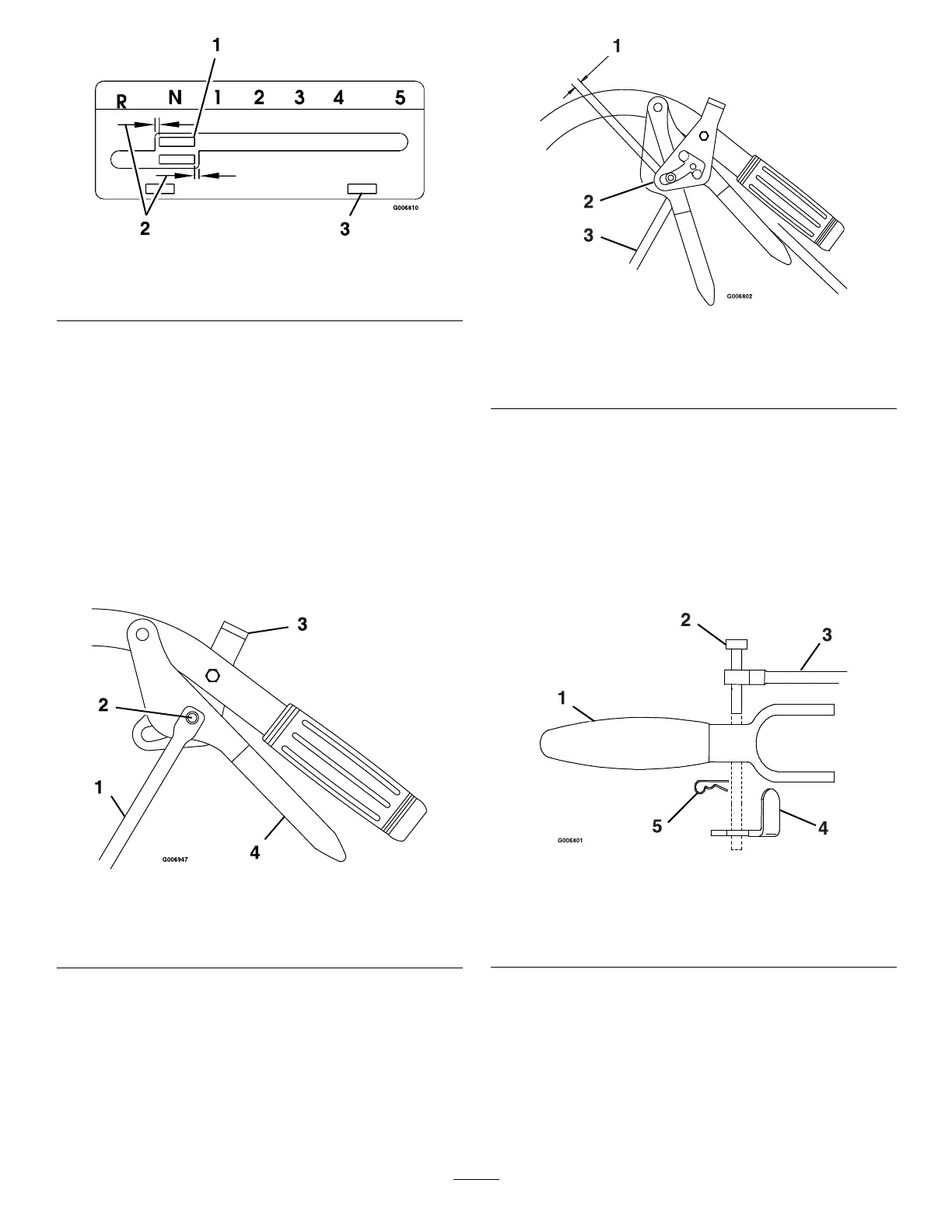
Figure6
1.Shifterlever
3.Adjustmentslots
2.Equaldistance
InstallingandAdjustingtheWheel
DriveLinkages
ForPistolGripHandles:
1.Screwthethreadedendofthedrivelinkagesintothe
swivelsinthewheeldriveidlerarms.
2.Inserttheclevispinfromtheboltbagthroughthe
drivelinkage,theleverandtheslotintheneutral
lock/parkbrakelatches(Figure7).Maketheproper
adjustmentsbeforeaddingthehairpins.
Figure7
1.Drivelinkage
3.Neutrallock/parkbrake
latch
2.Clevispin
4.Drivelever
3.Adjustthedrivelinkagelengthbythreadingitinto
oroutoftheswiveluntilthereisa3/16inchto
1/4inch(4.7mmto6.4mm)clearancebetweenthe
linkageassemblyandthebottomoftheslotinthe
neutrallock/parkbrakelatch(Figure8).
Figure8
1.3/16inchto1/4inch(4.7mmto6.4mm)
2.Neutrallock/parkbrakelatch
3.Drivelinkage
Note:Theneutrallock/parkbrakelatchclearance
shouldbecheckedwherethereisaslightupward
forceplacedonthedriveleverstoremoveany
“slack”inthelinkage.
4.Aftertheclevispinhasbeeninserted,installthe
hairpinintotheholeontheclevispinbetweenthe
neutrallock/parkbrakelatchandthedrivelever
(Figure9).
Figure9
1.Drivelever
4.Neutrallock/parkbrake
latch
2.Clevispin
5.Hairpin
3.Drivelinkage
5.Repeattheprocedureonoppositesideofunit.
ForECSHandles:
1.Locatethedriveleverlinkageswhichhavethe
balljointandthejamnutsinstalledononeend.
Locatetwo5/16-18x13/4inchhexcapscrewsand
two5/16-18inchnylocnutsintheboltbag.
4
 Loading...