- 14 -
3.7.3 Lift up on support frame until it clears the support pins. Position support frame
so the arms are on each side of the tractor engine deck and secure.
For FMD523 and 603 units: Secure using eight (8) 3/8-16 x 1” bolts, disc spring
washers, and whizlock nuts.
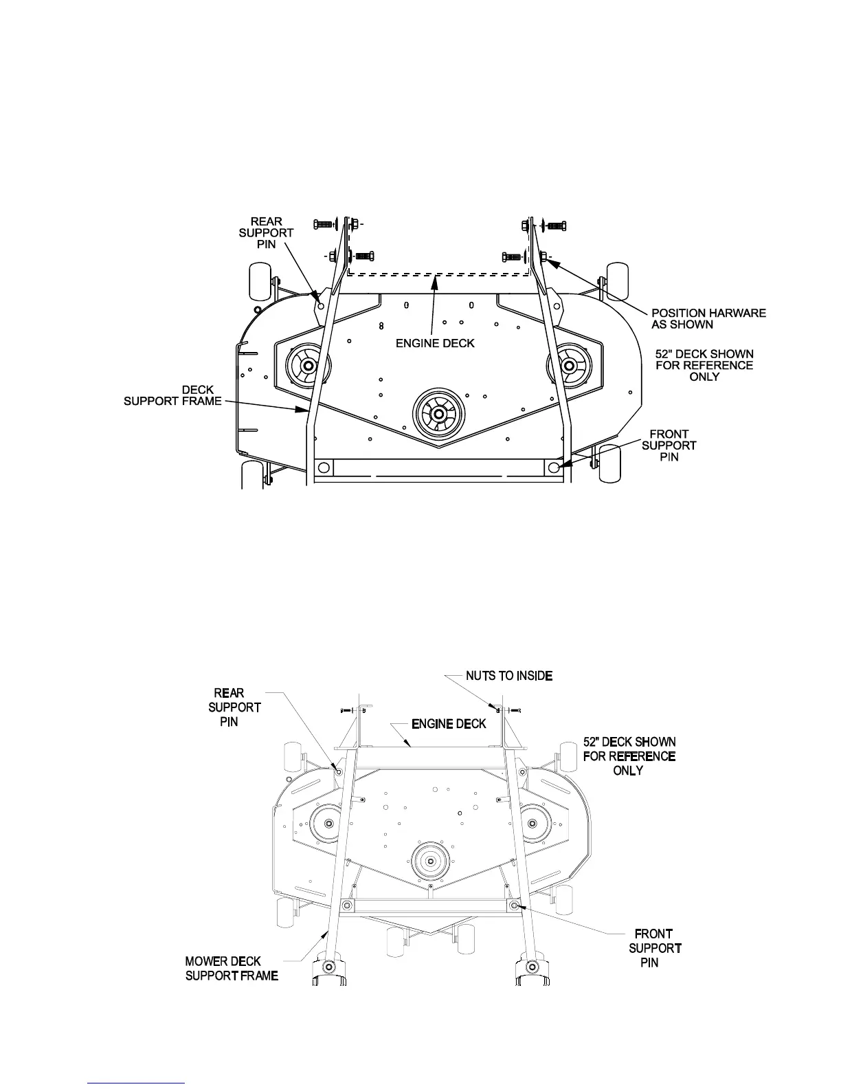
NOTE: Place spring washer cone against bolt head and install with the whizlock
nut to the inside of engine deck for the two rear holes on both sides. Install
whizlock nut to the outside for the two front bolt holes on each side of the mower
deck support frame (See Figure 1). Tighten until spring washers are flat.
FIGURE 1
HARDWARE AND SUPPORT PIN
LOCATION FOR DECK SUPPORT FRAME
For FMD524 and 604 units: Secure using eight (8) 3/8-16 x 1 1/4” bolts, disc
spring washers, and whizlock nuts.
NOTE: Place spring washer cone side against bolt head (cupped side away from
head) and install to outside of support frame (as shown in Figure 2). Install with
whizlock nuts to the inside of engine deck. Tighten until spring washers are flat.
FIGURE 2
HARDWARE AND SUPPORT PIN
LOCATION FOR DECK SUPPORT FRAME
MOWER
 Loading...