Figure3
1.Throttlecontrollever
3.Clamp
2.Throttlecable—Located
onbottomsideofclamp.
4.Chokecable
InstallthePTOEngagement
Linkage
1.Installthebladeengagementlinkagetothebellcrank
ontheLeftHandsideoftheenginedeck.
2.Inserttherodthroughtheholefromtheoutsideand
fastenwithcotterhairpin(
Figure4).
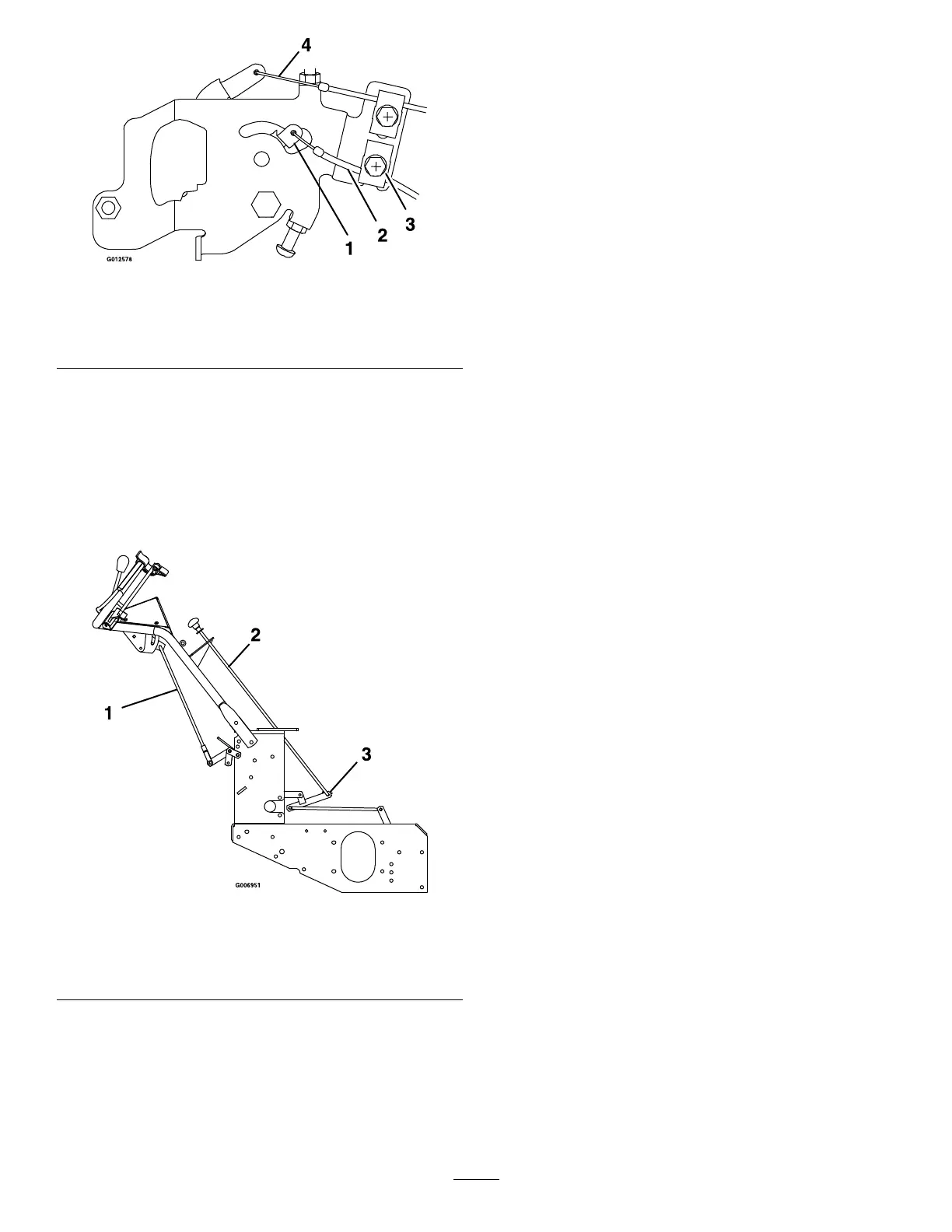
Figure4
1.Speedcontrolrod
assembly
3.Bellcrank
2.PTOengagementlinkage
InstallingtheSpeedControlRod
1.Locatethespeedcontrolrodassemblywithayoke
atoneend.
2.Inserttheendofthelinkageoppositetheyokeinto
theendofthespeedcontrolleverlocatedunderneath
thehandleconsolefromtherighthandsideand
fastenwithahairpinfromtheboltbag(
Figure4).
3.Connectthelowerendofthespeedcontrollinkage
tothespeedcontrolcranklocatedatthetoprearof
thefueltanksupport.Securewithaclevispinand
3/32x1/2inchcotterpin.
InstallingtheWheelDrive
Linkages
1.Positionthespeedcontrolleverinneutral.
2.Positionthedriveleversinneutralandengagethe
neutrallocklatches(
Figure5).
3.Threada3/8-24inchLHjamnut,fromtheboltbag,
ontothelowerendofeachdriveleverlinkage.
4.Identifythelowerballjointsinstalledonthehydro
controlarmweldments.Threadthelowerendof
eachdriveleverlinkageintothelowerballjointuntil
theholeinupperballjointalignswithholeindrive
lever.
5.Installa5/16-18x13/4inchhexcapscrewand
a5/8-18inchnylocnutoneachsideandtighten.
Thiswillgiveanapproximatesettingfordrivelever
linkages.
3