Tech-note
tn202-2.doc - 10.01.2012
ePALM10 Product Manual
12
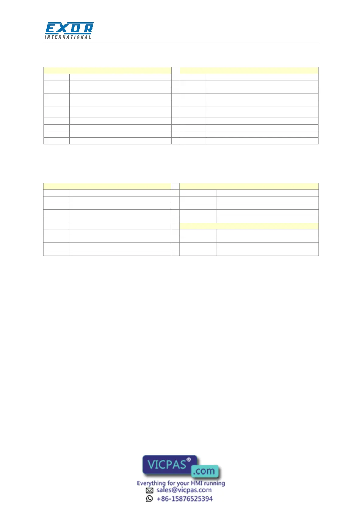
The assignment of the signals on the terminal blocks is shown in the tables below. Terminals
indicated as ‘Reserved’ should not be connected.
1 Aux Port pin 5 1 Reserved
2 Aux Port pin 9 2 Reserved
3 Aux Port pin 4 3 Reserved
4 Aux Port pin 8 4 Reserved
5 Aux Port pin 3 5 +5V output (max 100 mA)
6
Aux Port pin 7
6 GND
7 Aux Port pin 2 7 RXD
8 Aux Port pin 6 8 CTS
9 Aux Port pin 1 9 TXD
10 Reserved 10 RTS
The terminal assignment in CN1 refers to the corresponding assignment in the Aux Port of the
standard panel-mount version of the product. This correspondence will be useful to adapt the normal
cable drawings for use with the handheld device.
1 CHA+ 1 +24 VDC
2 CHA- 2 Common
3 CHB+ 3 Reserved
4 CHB- 4 PE
5 +5V output (max 100 mA)
6 GND
7 RXD 1 Enabling switch R (NO contact)
8 CTS 2 Enabling switch R (NO contact)
9 TXD 3 Enabling switch L (NO contact)
10 RTS 4 Enabling switch L (NO contact)
The Emergency Stop button is hardwired directly to the cable: the corresponding signals are not
available in the connectors.
The wires in the cable are color-coded according to the table below.
 Loading...