FRONT AND REAR PANELS
16
24. REVERSE LED:
This indicator will illuminate when the input power polarity to the
DUT is reversed.
25. GROUND LED:
This indicator will illuminate when the ground conductor to the
DUT is open. This is one of the single fault conditions which is simulated during the
leakage test.
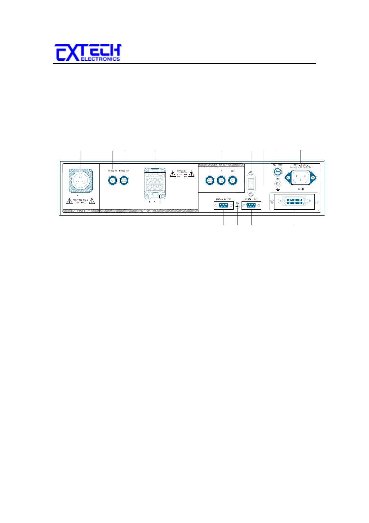
3.2 REAR PANEL DESCRIPTION
1. DUT POWER INPUT TERMINAL:
This connector is the LINE and NEUTRAL
input power connections. An external single phase unbalanced AC power supply with
a single Hot or Line conductor should be connected here, to supply power to the DUT
while performing the leakage test. This input is rated for 0-300 volts, 30 A maximum.
2. PROBE HI:
This terminal is an input to one side of the MD which is activated by
pressing the PROBE button #7, when the display indicates either P
H
-L or P
H
-P
L
for
performing Enclosure leakage or Applied Part leakage. This terminal and the PROBE
HI terminal # 25 on the front panel are connected in parallel during the Line Leakage
test. When the external link is active this terminal is isolated from the line leakage
test circuits.
3. PROBE LO:
This terminal is an input to one side of the MD which is activated by
pressing the PROBE button #7, when the display indicates P
H
-P
L
for performing
Applied Part leakage measurements. This terminal and the PROBE LO terminal # 24
on the front panel are connected in parallel during the Line Leakage test. When the
external link is active this terminal is isolated from the line leakage test circuits.
4. DUT OUTPUT TERMINAL:
This output terminal is where the LINE, NEUTRAL
and GND power connections from the adapter box is plugged into the Line Leakage
Tester. Line power is supplied to the DUT during the leakage test through this terminal.
This output is rated for 0-300 volts, 30 A maximum.
5. EXTERNAL MEASURING DEVICE CONNECTORS:
These connectors allow
the operator to connect an external Measuring Device circuit to the Line Leakage
Tester. These terminals are activated when the display indicates MD=F. The
1 23 4
10 11 12 13
5
67
8
9