FRONT AND REAR PANELS
17
external measuring device may allow the operator to test to a different standard,
which calls for a different measuring device, or to easily change the measuring device
if the standard requirements change.
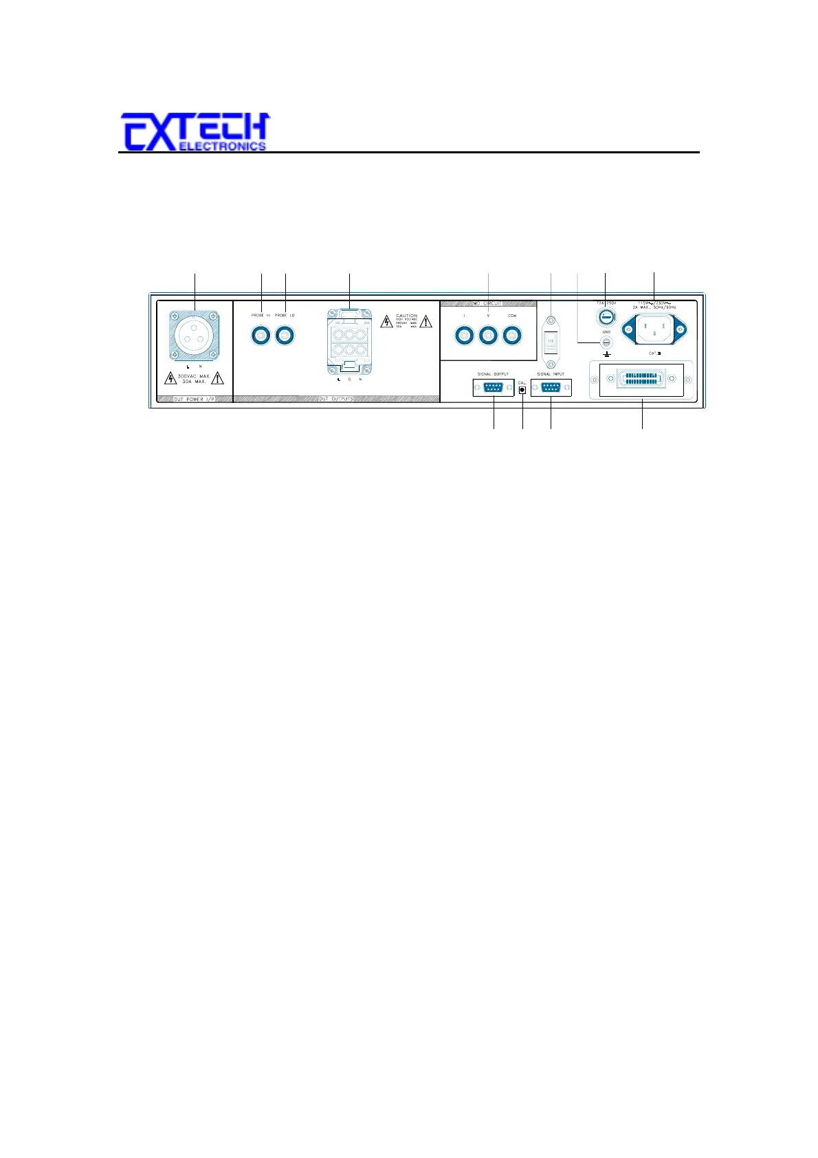
6. INPUT POWER SWITCH:
Line voltage selection is set by the position of this
switch. In the down position it is set for 110-120 volt operation, in the up position it
is set for 220-240 volt operation.
7. CHASSIS GROUND (EARTH) TERMINAL:
This terminal should be connected
to a good earth ground before operation.
8. FUSE RECEPTACLE:
To change the fuse unplug the power (mains) cord and turn
the fuse receptacle counter-clockwise. The fuse compartment will be exposed.
Please replace the fuse with one of the proper rating.
9. INPUT POWER RECEPTACLE:
Standard IEC 320 connector for connection to a
standard NEMA style line power (mains) cord.
10. REMOTE SIGNAL OUTPUT:
9-Pin D subminiature female connector for
monitoring PASS, FAIL, and PROCESSING output relay signals.
11. CALIBRATION ENABLE KEY:
This key is used during power up to enable the
calibration routines.
12. REMOTE SIGNAL INPUT:
9-Pin D subminiature male connector for remote
control of test and reset functions as well as program memory selection 1, 2, or 3.
13. GPIB:
Standard connector for interconnection to the GPIB interface. Optional RS-
232 interface can be substituted for this interface.
1 23 4
10 11 12 13
5
678
9