TEST PARAMETER SETUP PROCEDURES
29
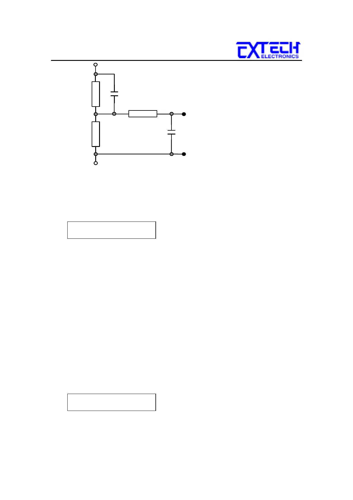
0.22
F
0.022
F
500
Ω
1.5K
Ω
10K
Ω
MD = E
The display will indicate the Measuring Device in the center of the first line of the
LCD display. The Measuring Device is indicated with letters A through F.
Measuring Device A will be displayed as follows:
1 . 0 s A 110.2V
M1-1
_
G-L
2500
µ
A
To change the Measuring Device, press the MD CIRCUIT key. The Measuring
Device will change each time the key is pressed, in sequential order. When the
display indicates the desired Measuring Device, the test is ready to start. No other
key strokes are necessary to save the configuration. The Measuring Device settings
are automatically saved into memory.
7.7 Connect Configuration
The connect feature of the Line Leakage Tester allows the instrument to link the
individual STEP configurations together into a sequence of tests. Each of the eight
steps within a memory location can be linked together, as well as linking the last
step of a memory to the first step of the next memory. Therefore the possibility
exists to link 400 different configurations together as one test sequence.
To change the connect configuration for an individual step, press the CONNECT
key. An underbar character will be present next to the Step number when the
connect feature is turned ON. The display will indicate the connection as follows:
1 . 0 s A 110.2V
M1-1
_
G-L
2500µ A
By pressing the CONNECT key again, the underbar character will be removed and
replaced with a blank space and Step connection will be turned OFF.