RS232 & GPIB INTERFACE
47
Tester. After the command is sent a GPIB read command must follow to retrieve
the data from the instrument in GPIB operation. In RS-232 operation the Line
Leakage Tester will automatically send the results to the data buffer at the
controller.
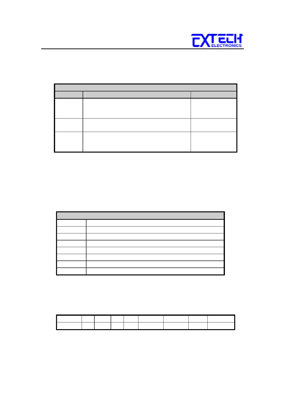
Query Commands
Command Description Bytes Returned
?n
n=1-16
Returns the results of the test that was
executed on the nth step from the start of the
test sequence.
40 bytes
?K LCD READ used for active polling if the
active LCD display during or after the test.
40 bytes
?D Read the status of the Reset input 1 byte
0 = OFF
1 = ON
The “n” within the read buffer command ?n represents the number of the test in a
sequence of tests and not the actual step number. The test number starts with 1 as
the first test performed. For example, if three steps were executed as a sequence,
using steps 5, 6 and 7, the results from step 5 will be retrieved from the 1st buffer
using the ?1 command not ?5.
12.8.4 GPIB Service Request
SRQ Configuration Settings
F0 Enable “All Pass” SRQ
F1 Disable “All Pass” SRQ
F2 Enable “Fail” SRQ
F3 Disable “Fail” SRQ
F4 Enable “Abort” SRQ
F5 Disable “Abort” SRQ
F6 Enable “Error Command” SRQ
F7 Disable “Error Command” SRQ
The service request capability is not available with the RS-232 interface. The
service request status byte can be read from the instrument only after one or more
of the service request functions have been enabled. The status byte bit
assignments are as follows.
BIT 7 6 5 4 3 2 1 0
Function na RQS na na ERROR ABORT FAIL PASS
The bit will be active or 1 when the SRQ function has been enabled and the
condition is true. Bit 6 is the RQS bit and will be active when the instrument has