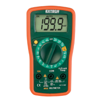
Continuity Measurements (Remove power or voltage from the device under test)
1. Connect the black test lead to the COM-socket and the red lead to the VΩ socket.
2. Set the rotary switch to the "Continuity" symbol position
3. The continuity buzzer will sound if the measured resistance is < 30Ω
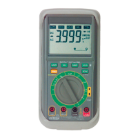
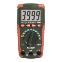
Battery Measurements (MV-110 only)
1. Connect the black test lead to the COM-socket and the red lead to the VΩ socket.
2. Set the rotary switch to the 1.5V or 9V position
3. The meter will display the voltage under load of the tested battery.
Square Wave Output
(MV-110 only) Note: Remove power or voltage from the device under test
1. Connect the black test lead to the COM-socket and the red lead to the VΩ socket.
2. Set the rotary switch to the "square wave symbol" position
3. The meter will output a 50Hz square wave.
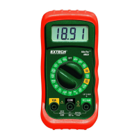
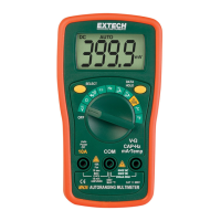
Capacitance Measurements (MV-120, MV-130 only) Note: Remove power or voltage from the device under test
1. Insert the capacitor in the CAP socket.
2. Set the rotary switch to the proper capacitance position.
3. The value of the measured capacitor will appear in the LCD.