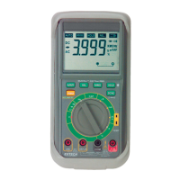
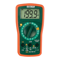
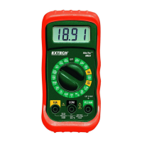
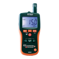
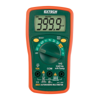
Diode Measurements
1. Connect the black test lead to the COM-socket and the red lead to the VΩ socket.
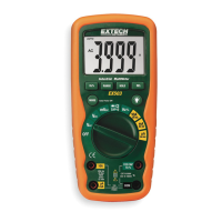
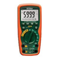
2. Set the rotary switch to the "Diode" symbol position
3. Connect the test leads to the diode under test.
4. The value of the forward voltage drop (0.3 to 0.6V) or the open circuit voltage (2.6V approx.) will appear in the
LCD display for a good diode.
AC/DC Current Measurements
(If the magnitude of current is unknown, select the highest meter range and then reduce the range as needed)
1. Connect the black test lead to the meter's COM-socket and the red lead to either the "A" socket if measuring less
than 2A or the "10A/20A" socket if measuring less than 10A or 20A
2. Set the rotary switch to the "A" position as required. Always select the highest range when unsure of the current
value.
3. Press the "DC / AC" button to select AC or DC measurement.
4. Connect the test leads in series with the unit under test (load, circuit, etc.)
5. The value of the measured current will appear in the LCD.
6. Negative DC current will appear with a "-" sign.
NOTE: The mA and A ranges are protected by a 0.2A or a 2A fuse. The 10A or 20A ranges are not fuse protected.
Always replace blown fuses with fuses of the identical type.

 Loading...
