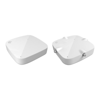
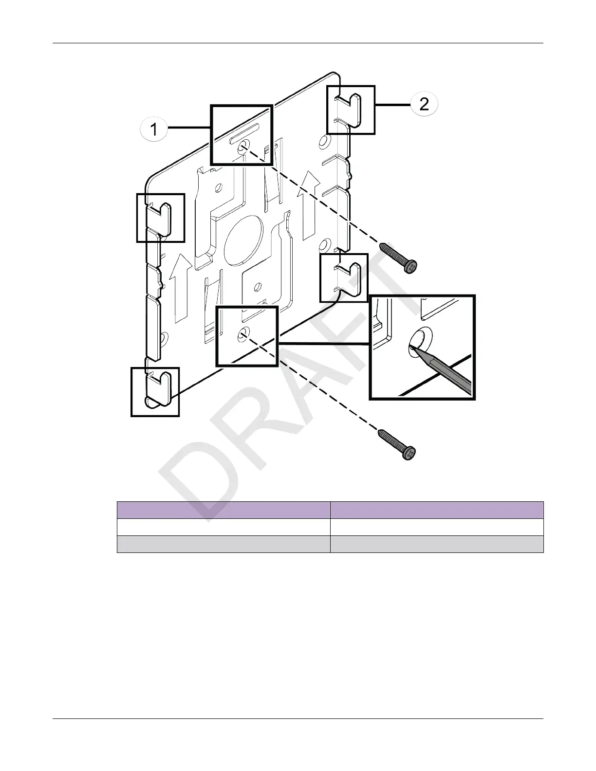
Figure 1: Main mounting bracket
Callout Description
1 Main mounting bracket mounting holes
2 Main mounting bracket feet
2. Insert the Phillips pan head screws into the main mounting bracket holes and attach the bracket to
the w
all.
Use screw-in anchors, if needed.
3. Connect the Ethernet cable RJ45 connector into the GE1 port.
4. Place the access point onto the bracket feet and slide it down to lock it in place.
Install a Security Torx Locking Screw
About This Task
The security torx locking screw is used to prevent the access point from being removed from the main
mounting bracket (#37201). There are two security lock screw holes on the rear of the access point.
Install the Access Point
Install the Access Point Using the Main Mounting
Br
acket
ExtremeWireless™ AP310i/e Access Points 17
 Loading...