9XTP II CrossPoint Series • Installation
NOTE: See item
A
on figure 2 on page 4, figure 3 on
page 5, and figure 4 on page 6.
7
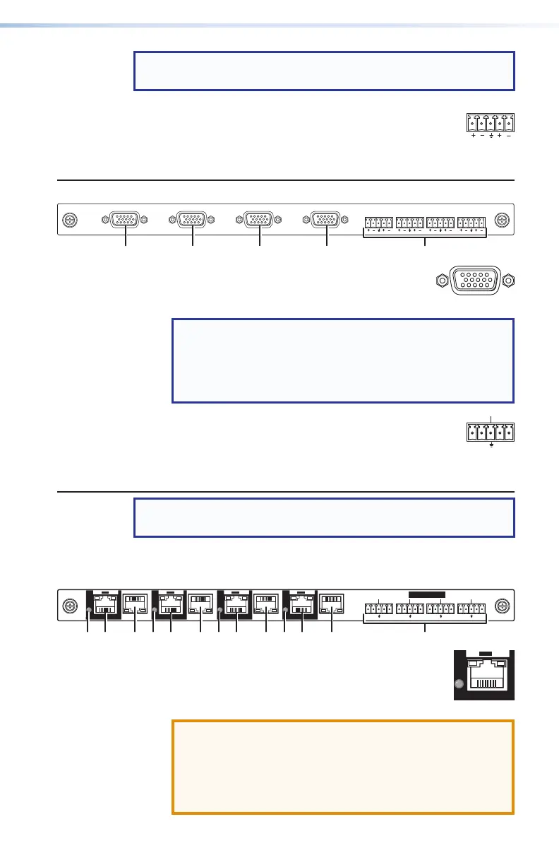
Audio (local audio) connectors — Connect
balanced or unbalanced stereo audio inputs to
these 3.5 mm, 5-pole captive screw connectors
(see Local audio connectors on page 17 to wire the
connectors).
XTP CP 4i VGA (universal analog video input board)
XTP CP 4i VGA
AUDIO
LR LRLR LR
IN
£
VGA connectors — Connect up to four VGA
cables between these ports and the analog
video output port of the video sources.
NOTE: This universal analog video board can accept
RGB video and (with adapters) component video,
S-video, and composite video (see Analog video
connectors on page 17 to wire the connectors for
various analog video formats).
7
Audio (local audio) connectors — Connect
balanced or unbalanced stereo audio inputs to
these 3.5 mm, 5-pole captive screw connectors
(see Local audio connectors on page 17 to wire the
connectors).
NOTE: See item
B
on figure 2 on page 4, figure 3 on
page 5, and figure 4 on page 6.
B
Output boards space — Install output boards.
XTP CP 4o and XTP CP 4o 4K (XTP output boards)
OUT
XTP CP 4o
RS-232 IR
Tx Rx Tx Rx
RS-232 IR
Tx Rx Tx Rx
RS-232 IR
Tx Rx Tx Rx
RS-232 IR
Tx Rx Tx Rx
SIG LINK
XTP
PWR
LAN
XTP
PWR
LAN
XTP
PWR
LAN
XTP
PWR
LAN
IR/RS-232 OVER XTP
SIG LINK SIG LINK SIG LINK
11111111333333332244222222
1
XTP output connectors — Connect a TP cable
between this connector and a compatible Extron
XTP receiver (see TP connectors on page 13
to wire the connector).
ATTENTION:
• Do not connect these ports to a computer data or
telecommunications network.
• Ne connectez pas ces ports à des données
informatiques ou à un réseau de télécommunications.
PWR

 Loading...


