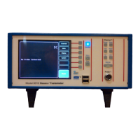
F.W. BELL 8000 Series Gauss/Tesla Meter Instruction Manual
v
LIST OF ILLUSTRATIONS
Figure 1-1 Front Panel (8010 Model Shown) ............................................................ 1-6
Figure 1-2 Rear Panel (8010 Model Shown) ............................................................. 1-7
Figure 1-3 Various Positions of Meter ....................................................................... 1-8
Figure 2-1 Frequency Response of Uncorrected Analog Output ............................... 2-3
Figure 2-2 Digital I/O Connector ................................................................................ 2-4
Figure 2-3 YA-111 Zero Flux Chamber ..................................................................... 2-6
Figure 2-4 YA-112 Zero Flux Chamber ..................................................................... 2-6
Figure 3-1 8000 Series Probe Model Chart ............................................................... 3-2
Figure 3-2 Hall Probe Configurations ........................................................................ 3-4
Figure 4-1 Probe Electrical Warning .......................................................................... 4-2
Figure 4-2 Fuse Replacement ................................................................................... 4-3
Figure 4-3 Adjusting the Handle and Feet ................................................................. 4-4
Figure 4-4 Installing and Removing Probes .............................................................. 4-5
Figure 4-5 Standby Button Location .......................................................................... 4-6
Figure 4-6 Boot Up Screen ........................................................................................ 4-7
Figure 5-1 Front Panel Key Sets ............................................................................... 5-2
Figure 5-2 Main Menu Example ................................................................................ 0-3
Figure 5-3 Menu Selections Example ........................................................................ 5-4
Figure 5-4 Special Menu Screens ............................................................................. 5-4
Figure 5-5 8000 Gaussmeter Menu Map ................................................................... 5-5
Figure 6-1 Setting the Units ....................................................................................... 6-2
Figure 6-2 Flux Density Reading ............................................................................... 6-3
Figure 6-3 Range Settings ........................................................................................ 6-3
Figure 6-4 Measurement Mode Selection ................................................................. 6-5
Figure 6-5 Frequency / Period Indicator .................................................................... 6-5
Figure 6-6 Analog Filter Selection ............................................................................. 6-7
Figure 6-7 Auto Zero Menu Path ............................................................................. 6-10
Figure 6-8 Manual Zero Menu Path ......................................................................... 6-11
Figure 6-9 Update Interval Setting........................................................................... 6-12
Figure 6-10 Hold Features Settings......................................................................... 6-14
Figure 6-11 Relative Value Indicator ....................................................................... 6-16
Figure 6-12 Relative Settings Menu Path ................................................................ 6-17
Figure 6-13 8000 Series 3-Axis Probe Orientation .................................................. 6-18
Figure 6-14 Vector Sum Equation ........................................................................... 6-19
Figure 6-15 Vector Sum Relative Equation ............................................................. 6-19
Figure 6-16 Vector Sum Settings ............................................................................ 6-20
Figure 6-17 Analog Output Settings ........................................................................ 6-23
Figure 6-18 Example Circuit for Classifier Outputs.................................................. 6-24
Figure 6-19 Probe Output versus Flux Angle .......................................................... 6-25
Figure 6-20 Probe Output versus Distance ............................................................. 6-25
Figure 6-21 Flux Density Variations in a Magnet ..................................................... 6-26
Figure 7-1 AC Waveform Display Layout .................................................................. 7-1
Figure 7-2 Waveform Display Menu .......................................................................... 7-2
Figure 7-3 Trigger Setup Menu ................................................................................. 7-4

 Loading...