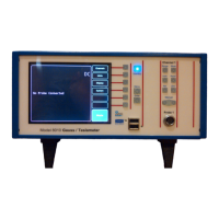
F.W. BELL 8000 Series Gauss/Tesla Meter Instruction Manual
vi
Figure 8-1 RS-232 Connector ................................................................................... 8-3
Figure 8-2 RS-232 Setup Screen .............................................................................. 8-3
Figure 8-3 Ethernet Connector Pin Out ..................................................................... 8-4
Figure 8-4 Network Configuration Screen ................................................................. 8-5
Figure 8-5 Windows TELENET Example .................................................................. 8-6
Figure 8-6 8030 Gaussmeter Web Application Screen ............................................. 8-7
Figure 8-7 IEEE-488 (GPIB) Connector .................................................................. 0-10
Figure 8-8 GPIB Configuration Screen .................................................................... 8-12
Figure 8-9 Condition, Event, and Enable Registers ................................................ 8-13
Figure 8-10 Status Byte and SRQ Enable Register................................................. 8-14
Figure 8-11 Standard Event Register ...................................................................... 8-16
Figure 8-12 Measurement Event Register ............................................................... 8-16
Figure 8-13 Operation Event Register ..................................................................... 8-17
Figure 8-14 Questionable Event Register ............................................................... 8-17
Figure 9-1 Data Logging Menu Path ......................................................................... 9-2
Figure 9-2 Example of Waveform Mode Screen Capture .......................................... 9-3
Figure 10-1 Firmware Update Screen ..................................................................... 10-1
Figure A-1 Flux Lines of a Permanent Magnet .......................................................... A-1
Figure A-2 Hall Effect Sensor .................................................................................... A-2
Figure B-1 Two Dimensional Coordinate System ...................................................... B-1
Figure B-2 Vector Angle in a Two Dimensional System ............................................ B-2
Figure B-3 Three Dimensional Coordinate System ................................................... B-3
Figure B-4 Vector Angles in a Three Dimensional System ........................................ B-3

 Loading...