Page 5
October, 2005
415 L LS Operator And
425 D Control Panel Installation Manual
UNPACKING THE OPERATOR
When you receive your 415 L LS Compact Operator,
complete the following steps.
Inspect the shipping box for physical damage such as a
torn carton. Then inspect the operator after you remove
it from the box. Notify the carrier immediately if you
note any damage because the carrier must witness the
damage before you can file a claim.
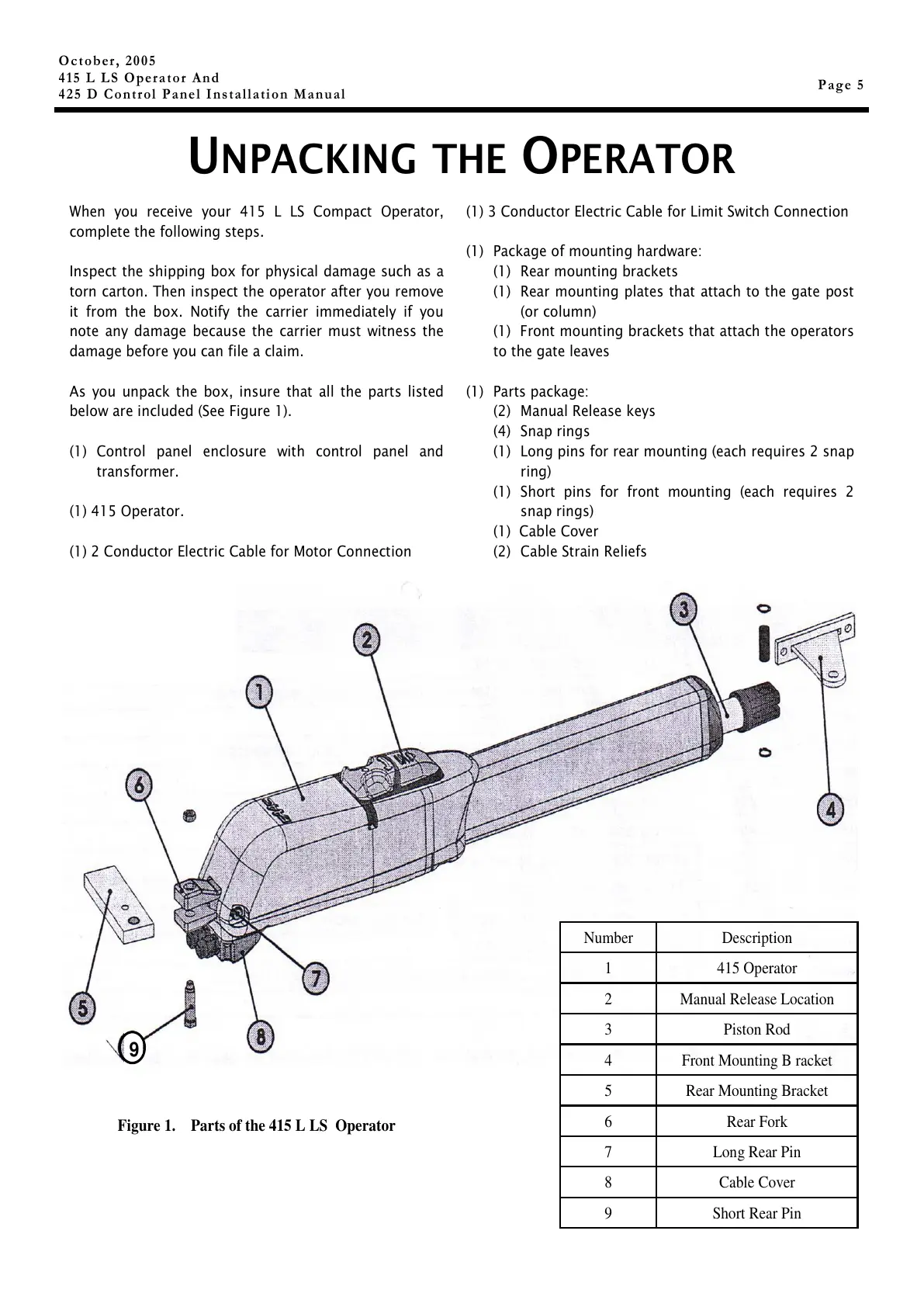
As you unpack the box, insure that all the parts listed
below are included (See Figure 1).
(1) Control panel enclosure with control panel and
transformer.
(1) 415 Operator.
(1) 2 Conductor Electric Cable for Motor Connection
Figure 1. Parts of the 415 L LS Operator
(1) 3 Conductor Electric Cable for Limit Switch Connection
(1) Package of mounting hardware:
(1) Rear mounting brackets
(1) Rear mounting plates that attach to the gate post
(or column)
(1) Front mounting brackets that attach the operators
to the gate leaves
(1) Parts package:
(2) Manual Release keys
(4) Snap rings
(1) Long pins for rear mounting (each requires 2 snap
ring)
(1) Short pins for front mounting (each requires 2
snap rings)
(1) Cable Cover
(2) Cable Strain Reliefs
9
Number Description
1 415 Operator
2 Manual Release Location
3 Piston Rod
4 Front Mounting B racket
5 Rear Mounting Bracket
6 Rear Fork
7 Long Rear Pin
8 Cable Cover
9 Short Rear Pin