3. Turn the manual release knob clockwise 1/2 turn.
4. To re-engage the operator, perform the procedure
in reverse.
Now the 415 operator is manual released. You can
move the gate freely.
ATTACH THE ELECTRIC CABLES
Before mounting the operator to the gate panel you
must attach the two provided electric cables. See figure
3 & 4 for the detail sticker on the bottom of the
operator.
Page 7
October, 2005
415 L LS Operator And
425 D Control Panel Installation Manual
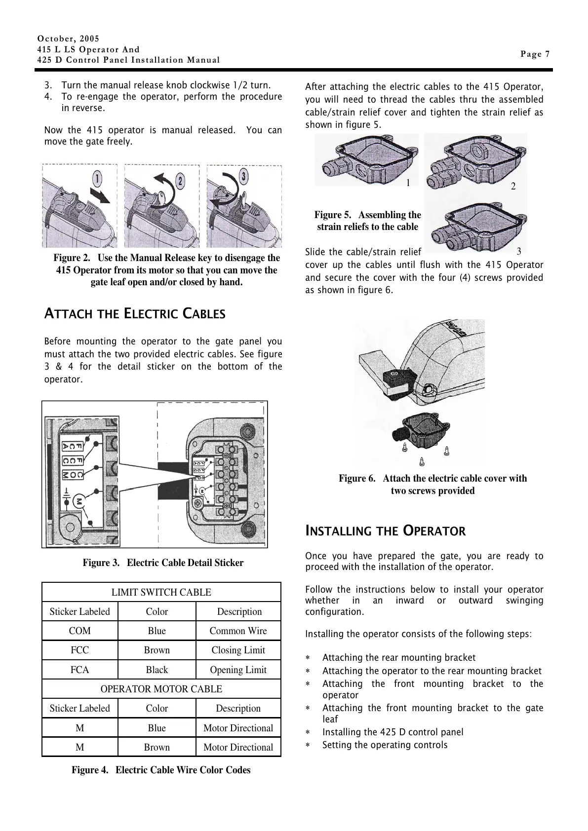
After attaching the electric cables to the 415 Operator,
you will need to thread the cables thru the assembled
cable/strain relief cover and tighten the strain relief as
shown in figure 5.
Slide the cable/strain relief
cover up the cables until flush with the 415 Operator
and secure the cover with the four (4) screws provided
as shown in figure 6.
I
NSTALLING THE OPERATOR
Once you have prepared the gate, you are ready to
proceed with the installation of the operator.
Follow the instructions below to install your operator
whether in an inward or outward swinging
configuration.
Installing the operator consists of the following steps:
∗ Attaching the rear mounting bracket
∗ Attaching the operator to the rear mounting bracket
∗ Attaching the front mounting bracket to the
operator
∗ Attaching the front mounting bracket to the gate
leaf
∗ Installing the 425 D control panel
∗ Setting the operating controls
Figure 6. Attach the electric cable cover with
two screws provided
Figure 2. Use the Manual Release key to disengage the
415 Operator from its motor so that you can move the
gate leaf open and/or closed by hand.
Sticker Labeled Color Description
COM Blue Common Wire
FCC Brown Closing Limit
FCA Black Opening Limit
OPERATOR MOTOR CABLE
Sticker Labeled Color Description
M Blue Motor Directional
M Brown Motor Directional
LIMIT SWITCH CABLE
Figure 5. Assembling the
strain reliefs to the cable
1
2
3
Figure 3. Electric Cable Detail Sticker
Figure 4. Electric Cable Wire Color Codes