Page 9
October, 2005
415 L LS Operator And
425 D Control Panel Installation Manual
A
D
B
E
C
F
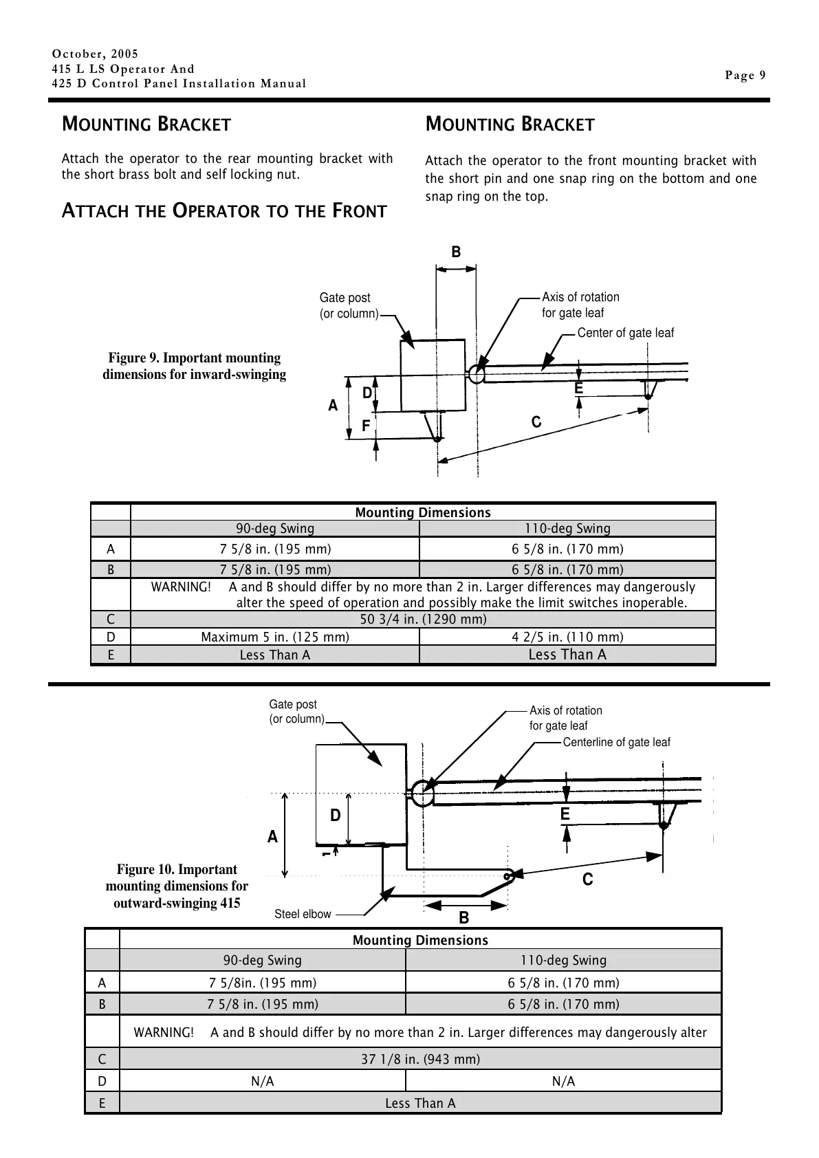
Gate post
(or column)
Axis of rotation
for gate leaf
Center of gate leaf
Figure 9. Important mounting
dimensions for inward-swinging
Axis of rotation
for gate leaf
Gate post
(or column)
Steel elbow
A
B
C
D
F
Centerline of gate leaf
E
Mounting Dimensions
90-deg Swing 110-deg Swing
A 7 5/8in. (195 mm) 6 5/8 in. (170 mm)
B 7 5/8 in. (195 mm) 6 5/8 in. (170 mm)
WARNING! A and B should differ by no more than 2 in. Larger differences may dangerously alter
C 37 1/8 in. (943 mm)
D N/A N/A
E Less Than A
Figure 10. Important
mounting dimensions for
outward-swinging 415
Mounting Dimensions
90-deg Swing 110-deg Swing
A 7 5/8 in. (195 mm) 6 5/8 in. (170 mm)
B 7 5/8 in. (195 mm) 6 5/8 in. (170 mm)
WARNING! A and B should differ by no more than 2 in. Larger differences may dangerously
alter the speed of operation and possibly make the limit switches inoperable.
C 50 3/4 in. (1290 mm)
D Maximum 5 in. (125 mm) 4 2/5 in. (110 mm)
E Less Than A
Less Than A
MOUNTING BRACKET
Attach the operator to the rear mounting bracket with
the short brass bolt and self locking nut.
ATTACH THE OPERATOR TO THE FRONT
M
OUNTING BRACKET
Attach the operator to the front mounting bracket with
the short pin and one snap ring on the bottom and one
snap ring on the top.